
Zero-Length Links in SAP2000
A zero-length link in SAP2000 and CSiBridge is a powerful and versatile modeling tool that allows engineers to introduce complex, localized force-deformation behavior at a single point without altering the model's geometry. It is a special type of Link element that connects two joints occupying the exact same coordinates, giving it a physical length of zero.
The behavior of the link is not based on its geometry but is entirely governed by user-defined properties assigned to it. This allows engineers to introduce specific phenomena into a structural model without altering the physical layout of the frames or elements.
Core Concepts and Applications
The primary function of a zero-length link is to model localized behaviors that are often nonlinear. By defining a specific force-deformation relationship across its six internal degrees of freedom (axial, shear, torsion, and bending), it can be used for a wide range of applications, including:
- Modeling Plastic Hinges: Simulating the nonlinear behavior of reinforced concrete frames for example.
- Seismic and Dynamic Analysis: Modeling the hysteretic behavior of seismic base isolators, dampers, and other energy dissipation devices.
- Contact and Pounding: Using "Gap" elements to simulate the interaction between structures that may come into contact during an event.
- Specialized Connections: Creating custom connections, such as friction bearings or elements with specific release conditions, like preventing the transfer of moments between members.
Local Coordinate System and Degrees of Freedom (DOF)
The link has six internal deformational degrees of freedom (one for each force and moment component) that can be independently configured. For each DOF, you can assign properties, keep it active, or fix it.
Link Properties The mechanical behavior of the link is defined through a Link Property. This property can be assigned various characteristics:
- Linear: Obeys linear elastic principles.
- Multi-linear Elastic: Follows a multi-stage linear force-deformation path.
- Nonlinear/Hysteretic: Utilizes advanced models to simulate complex behaviors, such as the Plastic (Wen) model for plasticity or the Rubber and Gap models for isolators and contact elements.
Practical Example: Preventing Torsion with a Scissor Connection
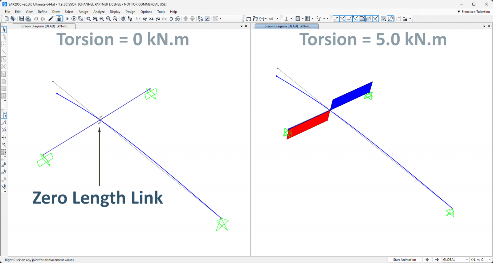
This tutorial demonstrates how to use a zero-length link to model a "scissor" behavior, where two orthogonal frames interact without transferring torsion to the supporting beam.
The image on the Left shows the desired outcome, while the image on the right shows the undesired torsion.
Step-by-Step Guide:
- Define Link Properties: Before creating the link element, define its mechanical properties via Define > Section Properties > Link/Support Properties. For this example, a property named "Lin1" would be created to simulate a moment release in rotation about the R2 axis (Ry).
- Isolate the Connection Point: To insert a link, you need two separate joints. The cleanest method is to temporarily move one of the intersecting elements.
- Select the frame member to be moved.
- Use the Edit > Move command (Ctrl+M) to displace it by a known distance (e.g., 1 meter in the Z-direction). This disconnects the member from the original joint and creates a new, separate joint at its endpoint. You now have two distinct joints where there was previously only one.
- Merge Numer: At this stage, you can assign different merge numbers to each node, allowing two joints to coexist at the same coordinates. This is a key step.
- Draw the Link Element: With two separate joints available, you can now draw the link.
- Go to Draw > Draw 2 Joint Link.
- Click on the first joint (the original one) and then on the second joint (at the end of the moved frame). A new link element will appear, spanning the temporary gap.
- Go to Draw > Draw 2 Joint Link.
- Reposition the Frame Member: The final step is to move the frame member back to its original position, making the link a true zero-length element.
- Select the previously moved frame and use the Edit > Move command again, this time applying the opposite displacement (e.g., -1 meter in the Z-direction).
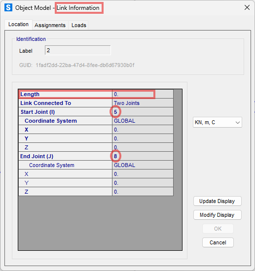
The two joints connected by the link are now coincident, and the link has a length of zero, effectively controlling the interaction between the two frames as defined by its properties. You can verify this by checking the Link Information window, which will show a length of zero and identical coordinates for joints I and J.
For a detailed, step-by-step visual guide on this process, watch the video below: