
How to Guarantee Compatibility Between Shell and Solid Finite Elements in SAP2000
Introduction
Combining Shell and Solid (3D) elements in finite element models allows you to represent, within the same model, slabs, walls, and plates connected to regions with greater thickness/volume, such as foundation blocks and other massive elements. However, these two element types have different formulations and degrees of freedom: Solids have only 3 translational DOFs per node, while Shells include 3 translations and 3 rotational DOFs per node, which are necessary to properly represent flexural behavior.
If the Shell–Solid interface is modeled only by matching nodes, without any additional care, kinematic incompatibilities often arise. These manifest as numerical instabilities, non-physical deformed shapes, spurious rotations, and unrealistic internal force distributions. The solution is to introduce appropriate kinematic constraints that allow consistent transfer of forces and moments between the shell and solid elements.
Example Objective
.png)
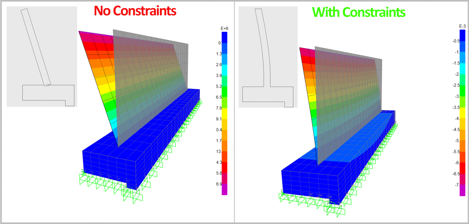
The example associated with the video (regardless of the specific geometry) aims to illustrate, in SAP2000:
- How to detect Shell–Solid interaction problems (instabilities, excessive displacements, anomalous rotations at the interface).
- How to understand the cause of these issues based on the difference in degrees of freedom between Shell and Solid elements.
- How to correct the interface by using “Weld” constraints (or equivalent), organized into small local node groups, in order to:
- Properly transfer bending moments and shear forces between Shell and Solid elements;
- Obtain a global deformed shape consistent with the expected structural behavior;
- Avoid overstiffening the entire interface.
- Obtain a global deformed shape consistent with the expected structural behavior;
- Properly transfer bending moments and shear forces between Shell and Solid elements;
Step-by-step in SAP2000
Base Modeling
Define geometry and element types:
- Model the wall region with Shell elements.
- Model the footing region with Solid elements.
- Ensure that, at the Shell–Solid interface, the nodes coincide.
Create load cases:
- Define at least one gravity load case (DEAD) including self-weight.
- Define an additional load case, Impulse, which starts from the final state of the DEAD case, so that predeformation and the stress state due to selfweight are considered before the additional action is applied.
Run an initial analysis:
- Run the analysis without defining any special links/constraints between Shell and Solid elements yet (just node matching between elements).
- Inspect the deformed shape and the solver messages.
Identifying Problems at the Interface
Check stability and deformed shape:
- If very large displacements/rotations occur in the connection area, or if you get messages about mechanisms/instabilities, this indicates that the Shell–Solid interface is poorly conditioned.
- At this point, it is important to recognize that the Solid element does not have rotational DOFs, and therefore the wall cannot correctly transfer its bending moments to the foundation with a simple nodal connection only.
Solution – Defining “Weld” Constraints
- In SAP2000, create a Weld-type Constraint with a 0.45 m tolerance to generate kinematic constraints between nodes along the interface.
- Define sets of 3 nodes that will behave as local rigid bodies.
- These groups allow the combination of nodal translations to reproduce an effective rotation, ensuring that the Shell bending moments are balanced by the stress field in the Solids.
Note on constraint interval/tolerance:
- In the Weld definition, specify a distance (tolerance) that controls which nodes belong to the same constraint group.
- Adjust this tolerance so that it is:
- Large enough to include all nodes intended to form one local rigid group (in this example, sets of 3 nodes spaced at 0.42 m);
- Smaller than the distance between adjacent groups (0.75 m in this example), so that two distinct groups are not merged into a single one, which would cause overconstraint.
New Analysis and Verification
Review the results:
- Confirm that instabilities and anomalous deformations at the connection zone have disappeared.
- Check whether the global deformed shape is consistent with the expected behavior (for example, effective fixity, appropriate rotation, and continuous curvature).
- Examine the distribution of internal forces (moments in Shell elements, stresses in Solid elements) near the interface, ensuring there are no artificial discontinuities or nearly zero forces where continuity is expected.
Video Demonstration
To follow this example, you can watch the video below, where we show directly in the SAP2000 model how to ensure a proper Shell–Solid connection, from identifying the initial issue to defining the Weld constraints and analyzing the final results.
Conclusions
Using Shell and Solid elements together in SAP2000 is extremely useful for modeling real structures, but it requires careful treatment of the interface due to the differences in degrees of freedom and formulation between these element types. Simple node matching is not enough to ensure correct transfer of rotations and bending moments, and can lead to instabilities and nonphysical behavior.
By creating Weld-type Constraints organized into local node groups, it is possible to locally enforce compatibility at the Shell–Solid interface, simulating an effective rotation and enabling realistic transfer of forces and moments, without overstiffening the entire system. Careful verification of global stability, deformed shape, and internal force distribution after implementing these links is essential to validate the quality of the model.
By following this procedure, the engineer can fully leverage the advantages of Shell and Solid elements, ensuring a robust and structurally sound interaction between them in SAP2000, clearly illustrated and complemented by the associated video.