
Seismic Capacity Design – Eurocode 8
As is widely recognized, Eurocode 8 sets strict criteria to ensure the ductility of primary seismic elements in structures subject to Medium (DCM) or High (DCH) ductility requirements.
This article focuses on the need to prevent brittle failures in plastic hinge zones. To that end, it addresses the specific issue of properly considering the lcl parameter (effective clear span) under Capacity Design as applied to beams.
Avoiding Brittle Failure Modes
To ensure proper beam performance, it is critical that seismic energy dissipation occurs through flexure rather than shear, as required by EC8.
- Flexural Plastic Hinging: This behavior is gradual and ductile, enabling the structure to sustain large deformations prior to collapse.
- Shear Failure: Conversely, shear failure is abrupt and brittle, compromising energy dissipation capacity and predictability of the structural response.
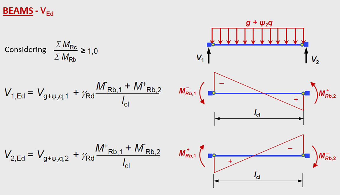
Capacity Design – EC8 Requirements
For primary seismic beams, Eurocode 8 requires that shear forces be designed with a capacity-based approach. Specifically:
- The design shear force (VEd) is calculated based on the sum of the plastic hinge moments of the beam sections (Mrd), divided by the effective clear span (lcl), plus the shear contribution from the quasi-permanent load combination.
This relationship is illustrated by the formula:
.png)
Here, Ved indicates the design shear force (424.706 kN in the example), compared with the installed design value (145.754 kN).

Significance of the lcl Parameter (Effective Clear Span)
El parámetro lcl, definido como la distancia libre efectiva entre las caras de los pilares, desempeña un papel decisivo en el dimensionamiento sísmico:
A smaller lcl increases shear forces for the same flexural capacity (Mrd), while a larger lcl reduces shear forces.
Correcting lcl in SAP2000 Modeling
In structural modeling using software such as SAP2000, frame elements (beams and columns) are generally represented by their geometric axes. If not properly adjusted, this can lead to inaccuracies, as the real clear span lcl is measured between the column faces, not their axes.

Solution with End Length Offsets
SAP2000 provides the End Length Offsets feature, which automatically adjusts beam and column ends to align the modeled axes with the actual column faces. This adjustment is essential for precise seismic design. In ETABS, this setting is enabled by default for both columns and beams.
Flexural Reinforcement Control – Mrd Calculation
When calculating the beam’s flexural capacity, the amount of longitudinal reinforcement at the ends can be obtained in two ways, in both SAP2000 and ETABS:
- Automatic Design: The software automatically calculates the longitudinal reinforcement based on analysis results, ensuring compliance with safety and ductility requirements.
- Manual User Definition: In cases of potential overdesign, the user must input this information into the program via “Reinforcement Overrides for Ductile Beams.” The resultant flexural strength will be the maximum between that derived from the specified reinforcement and that from the automatic design. Thus, capacity shear is calculated for the most unfavorable condition, i.e., the highest flexural strength.

Below is a summary of some of the ductility requirements for columns and beams, respectively.
Columns

Beams
We recommend reading the following CSI Portugal article for more details on all the Eurocode 8 ductility checks automatically performed by SAP2000, ETABS, and VIS.
