
A Guide to Moving Load Analysis in CSiBridge
For any structural engineer, particularly those beginning their careers in bridge design, understanding how to accurately analyze the effects of moving vehicles is a fundamental requirement. Bridges aren't static structures subjected to simple, unchanging forces; they are dynamic systems that must safely support the ever-shifting weight of traffic. CSiBridge is a powerful software that provides sophisticated tools to tackle this challenge through its Moving Load Analysis capabilities.
This guide will walk you through the essential concepts and procedures for performing moving load analysis in CSiBridge, turning a complex task into a manageable process.
The Core Components: Lanes, Vehicles, and Influence Lines
Before you can run an analysis, you need to define the basic components that simulate real-world traffic scenarios.
Lanes: Defining the Path of Travel
First, you must specify the paths that vehicles can travel across the bridge. In CSiBridge, these paths are called Lanes. A lane is not just a line; it has a defined length, direction, and can even have a varying width to model complex roadways like interchanges where lanes merge and split.
CSiBridge offers two primary types of lanes:
- Fixed Lanes: These have a specified, unchanging transverse (side-to-side) location on the bridge deck. You define exactly where they are.
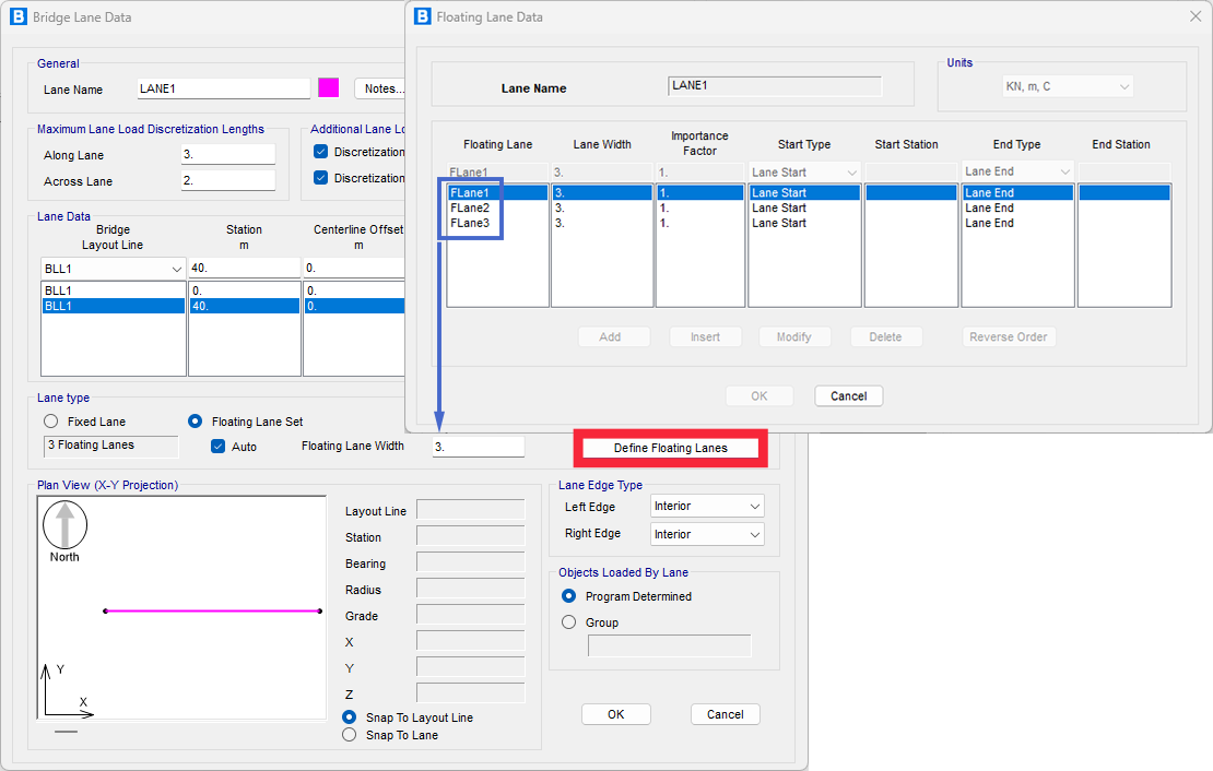
- Floating Lanes: This is a powerful, automated feature. You define a wider "Lane Set," and the software will automatically adjust the transverse position of the lane(s) within that set to find the location that creates the maximum force effect (like bending or shear) for each structural element. This is crucial for ensuring you capture the worst-case loading scenario without manual iteration. This option is permitted in some codes like ASSHTO.
Vehicles: Defining the Loads
Once you have lanes, you need to define the vehicles that will travel on them. CSiBridge allows for a high degree of customization to represent anything from standard design trucks (like AASHTO or Eurocode vehicles) to special-permit vehicles or trains.
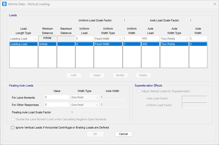
A vehicle is defined by its loads, which can include:
- Axle Loads: These are concentrated loads representing the wheels of a vehicle.
- Uniform Loads: These are distributed loads that can be specified between axles or extending infinitely before or after the vehicle, often used to simulate the presence of other traffic.
Historically, national bridge design codes, such as the British Standards, German DIN, and American AASHTO, had considerable differences in how they defined traffic loads. However, a significant effort in Europe has led to a harmonized approach through Eurocode 1, Part 2 (EC1-2).
The Eurocode's modern methodology is based on probabilistic models derived from statistical traffic data. It considers variables like vehicle categories, axle loads, and spacing to define design loads. These models are not meant to represent actual traffic but rather to simulate the most critical load effects—such as internal forces and displacements—that traffic can induce on the structure. This approach also directly incorporates the dynamic effects of moving vehicles.
A key concept in EC1-2 is the use of "notional lanes," which are standardized 3-meter-wide lanes used for applying the calculated loads. The number of notional lanes is determined by the total width of the bridge's carriageway. This systematic approach ensures that the design accounts for the worst-case loading scenarios in a consistent and statistically informed manner.
The following image shows the automatic generation of LM1 used in Eurocode.

Beyond simple vertical gravity loads, you can define horizontal forces to simulate real-world conditions:
Braking and Acceleration: Longitudinal forces that act parallel to the lane.
Centrifugal Forces: Transverse forces that occur when a vehicle travels along a curved path.
Influence Lines and Surfaces: The Key to Efficiency
How does the software find the worst-case scenario without having to simulate every possible vehicle position? The answer lies in influence lines and surfaces.
An influence line is a diagram that shows the value of a specific response (like moment, shear, or deflection) at a single point on the structure as a unit load moves across it. For a lane with width, this extends into an influence surface.
By generating these influence surfaces, CSiBridge can instantly see which parts of the lane will produce a positive (or negative) response. When it applies a vehicle load, it strategically places axles and uniform loads on the peaks and valleys of this surface to calculate the maximum and minimum possible responses. This is an incredibly efficient and powerful method for enveloping the effects of traffic.
The Analysis Procedures: Two Paths to Your Results
CSiBridge offers two distinct methods for moving load analysis.
Influence-Based Enveloping Analysis
This is the most common approach for design, as it provides an envelope of the maximum and minimum possible force results. The steps are straightforward:
- Model the Bridge: Create your structural model.
- Define Lanes: Lay out the paths for traffic.
- Define Vehicles: Specify the trucks or loads to be used.
- Create Vehicle Classes: Group one or more vehicles that should be considered together.
- Set Up a Moving-Load Case: This is where you bring everything together. You assign Vehicle Classes to specific Lanes and let the software work its magic using the influence surfaces.
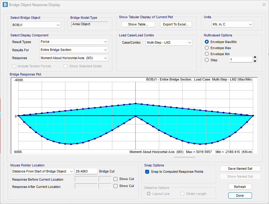
- Run the Analysis: CSiBridge will compute the enveloped responses for the elements you've specified. You can then view the maximum and minimum force diagrams to ensure your design is adequate.

Step-by-Step Analysis
This method is used when you need to understand the exact response of the bridge at specific moments in time as a vehicle crosses it. This is useful for studying dynamic effects or for cases where the sequence of loading is important.
The process is similar, but instead of creating a "Moving-Load Case," you:
- Define Load Patterns: Specify which vehicles move on which lanes, at what speed, and from what starting positions.
- Apply in Multi-Step Cases: Use these patterns in a Multi-Step Static or Time-History Load Case to simulate the vehicle moving incrementally across the structure.
- Run and View Results: You can view the results at each step, or even create a video to visualize the bridge's deflection and stress as the vehicle moves.
By mastering these concepts and procedures, new structural engineers can leverage the full power of CSiBridge to perform accurate, efficient, and safe moving load analyses, forming a solid foundation for a career in bridge engineering.