
Staged Construction – Using “Add Guide Structure” Operation
Staged construction analysis is essential for accurately simulating the real-world behavior of bridges built in phases. A significant challenge in modeling composite bridges—such as those with Precast Concrete and a cast-in-place slab—is accounting for the deformations that occur before the structure is fully assembled. The precast will deflect under their own weight before the slab is added. For an accurate analysis, the slab must be modeled in this already-deflected position.
The CSI software, provides a powerful feature to manage this exact scenario: the Guide Structure. This article provides a step-by-step guide on how to use this feature to model the staged construction of a bridge deck of a Precast Concrete U-Girder and a subsequently cast in place concrete slab.

Understanding Guide Structures
A guide object, or "guide," is a special type of element used in staged construction analysis. A guide object possesses the same geometry and connectivity as the actual structural element it represents. However, it has the following key characteristics:
- Negligible Stiffness and Mass: Guide objects for frames, tendons and homogeneous shells have negligible stiffness, mass, and weight. They do not contribute to structural resistance or loading.
- Cable guides have negligible stiffness compared to their actual objects, although they
- may still exhibit significant forces when taut or nearly taut.
- Joint Spring and Link guides exhibit full stiffness and nonlinear behavior, both for one-joint (support) and two-joint (connecting) links.
- Layered shell guides exhibit full stiffness and nonlinear behavior.
- No Applied Loads: Any loads applied to a guide object are ignored during the analysis.
- Deforms with the Structure: The primary purpose of a guide is to follow the deflections of the main structure. It acts as a geometric placeholder that moves with the joints of the active structure.
- Guide objects do not exhibit time-dependent behavior: creep, shrinkage, or age dependent stiffness.
When the actual object is added in a later construction stage, it replaces its corresponding guide object, inheriting its deformed position. This ensures that the newly added element starts its life in the correct, deflected shape of the structure, providing consistent and accurate deflection measurements.
Modeling Example: Staged Construction of a Precast U Girder Deck
Let's model a bridge deck consisting of a precast concrete U-girder and a cast-in-place concrete slab. The process is divided into multiple stages within the staged construction load case definition. A possible solution could be:
Stage 1: Add Structure “ALL_BUT_SLAB”
In this step, all components of the Bridge, excluding the Slab, will be added.
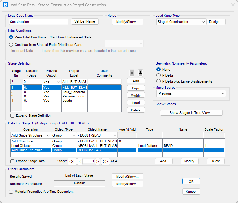
Before the main construction begins, the slab must be added to the model as a guide structure.
- In Stage 1 of your staged construction case, use the operation "Add Guide Structure".
- Select the group containing the shell objects that represent the bridge slab.
- The slab now exists in the model as a guide. It has no stiffness or weight but is connected to the nodes where the girders will eventually be placed.
As illustrated in the next image, the Slab Guide Structure correctly follows the girder's deformation. It is important to note that the slab itself carries no stress or force at this stage, functioning purely as a geometric guide.

A key technical point is that the connection between the slab and the U-girder joints is maintained using Joint Constraints. The Guide Structure is essential for this approach because, without it, these constraints would not be considered during the staged analysis. As a result, the entire slab would remain in its original position until it is added in a later stage.

By using a guide structure, engineers can accurately model the sequential construction of composite bridge decks in CSI software. This method ensures that elements added in later stages are introduced into the model in a state of realistic deformation, leading to a more precise analysis of stresses and long-term deflections. The process correctly separates the behavior of the precast elements from the final composite section, reflecting true construction practice.
Next article will cover the Pour and Remove Forms operations.
Simulating Cast-in-Place Concrete Bridges: Using Pour and Remove Forms Operations in CSI Bridge