
Buckling FEM in ETABS
Classical stability checks of steel structures rely on column or beam-column formulas with idealized boundary conditions and non-deforming cross-sections. They are fast and conservative, but they conceal what often governs slender members: local buckling of the web or flange, distortional modes, and the coupling between instabilities.
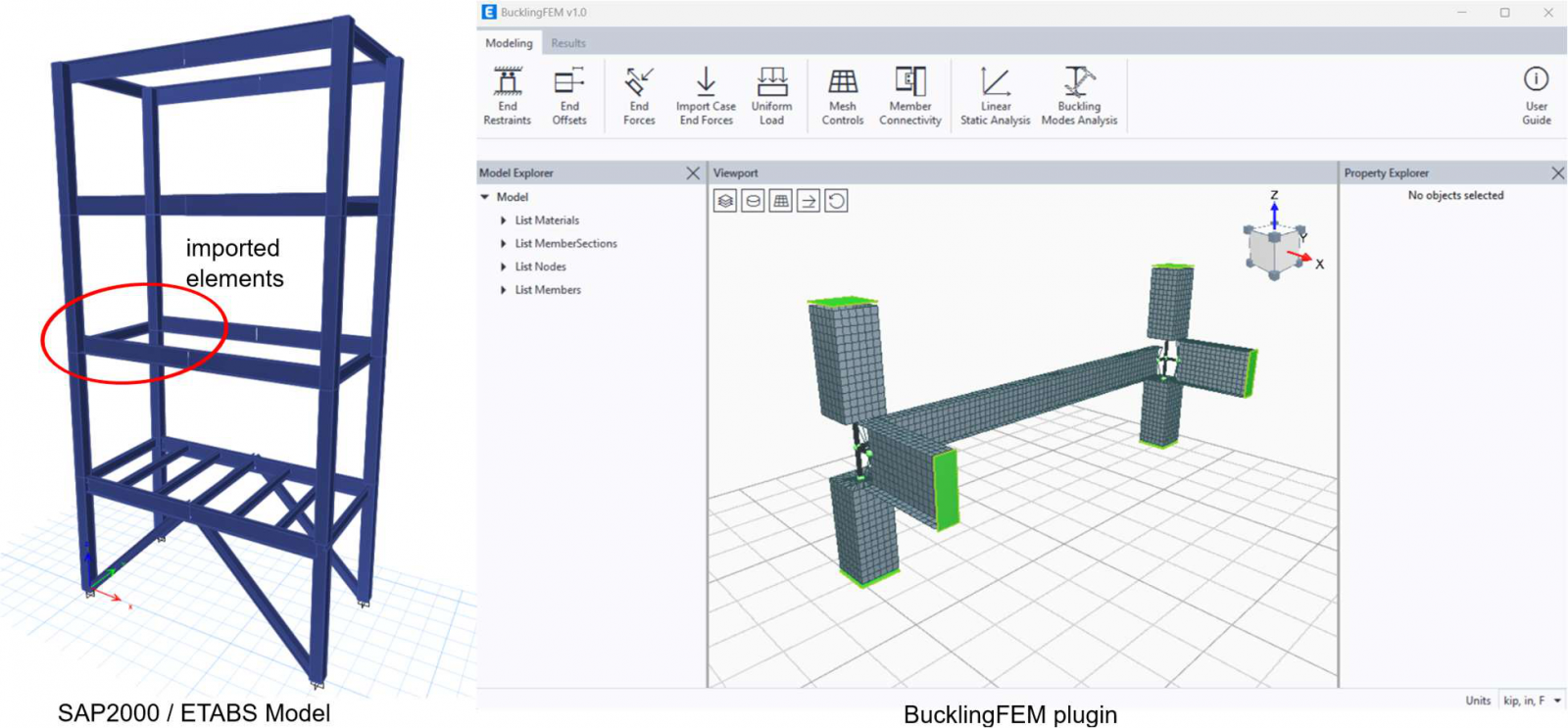
BucklingFEM, a plugin integrated in ETABS, fills this gap. Instead of reducing a section to a line, it discretizes it into shell elements and solves an eigenvalue problem to directly obtain critical loads and instability mode shapes. The result is a much more rigorous assessment of stability, without leaving the environment where the model is already built.
From frame model to shell element model
In ETABS, the user selects the elements of interest — typically a main member and those framing into it — and opens the plugin under Tools > BucklingFEM. Each frame element is automatically converted into a mesh of shell elements generated from the real cross-section geometry. By discretizing webs and flanges into finite elements, the module captures not only global buckling but also local modes that frame models inherently neglect.
The procedure captures only the elastic critical load, i.e., the bifurcation point. Geometric imperfections, residual stresses, and post-buckling response are not included unless explicitly introduced, so the resulting factors are idealized upper-bound estimates.
Connectivity between elements
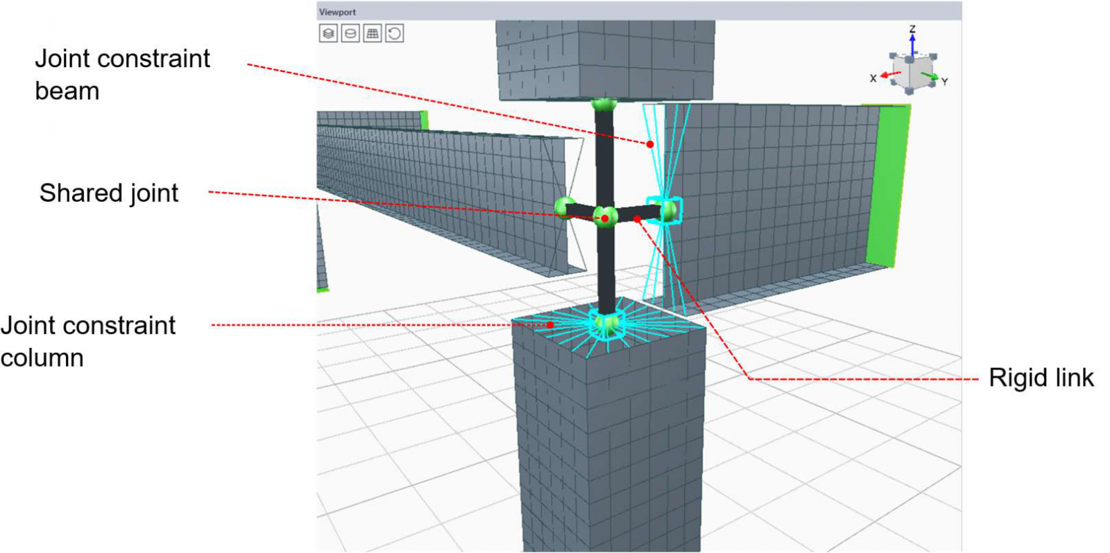
The rigid connection links all end nodes of an element to a Master Joint, which is then connected to the shared node via a rigid link. It applies only to elements sharing a common node and is created by default after import.
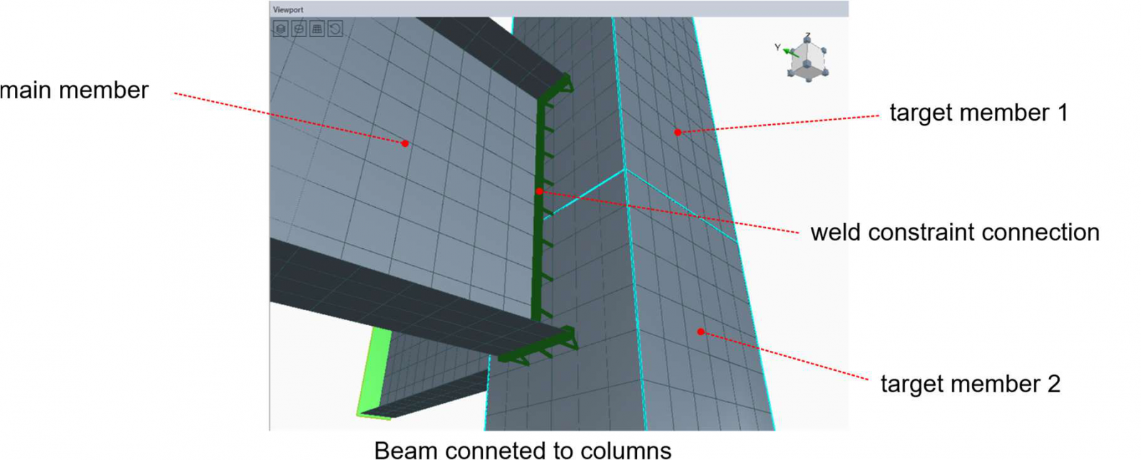
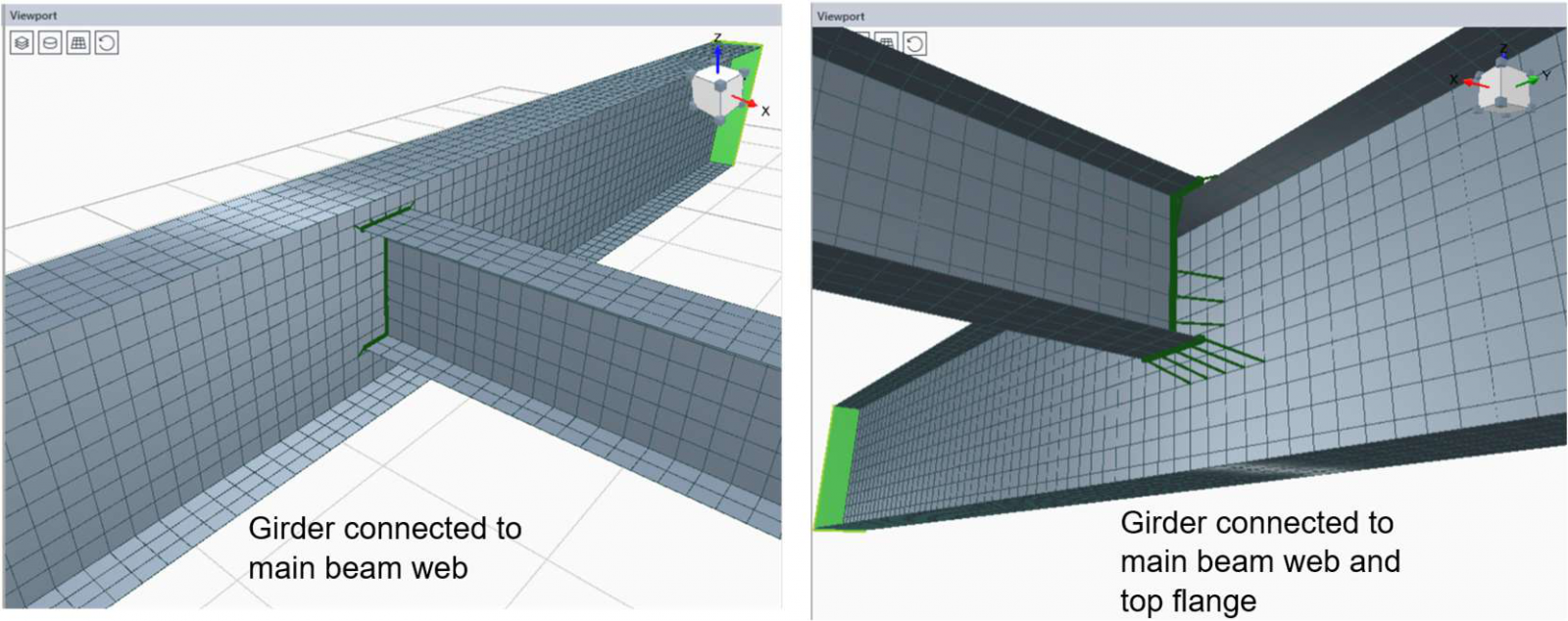
For elements that do not share a node, such as secondary beams connecting to primary beams through overlapping meshes, a Weld constraint is used. The program searches for the closest node pairs within a given tolerance and creates one constraint per valid pair. The first selected element is considered the main one.
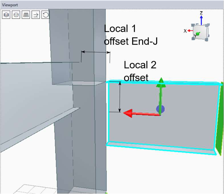
Offsets
The End Length Offsets (local axis 1, ends I and J) shorten or extend the element, while local offsets 2 and 3 introduce small transverse displacements equivalent to an Insertion Point.
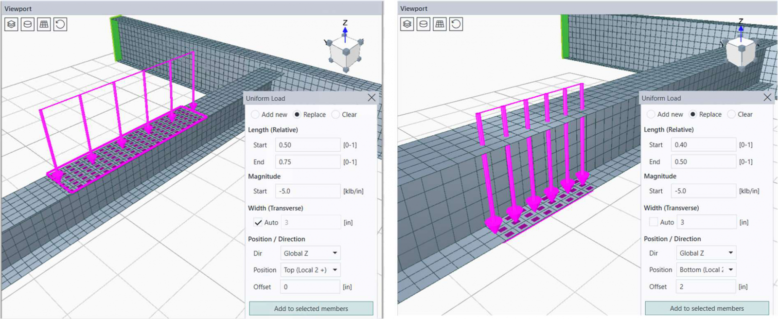
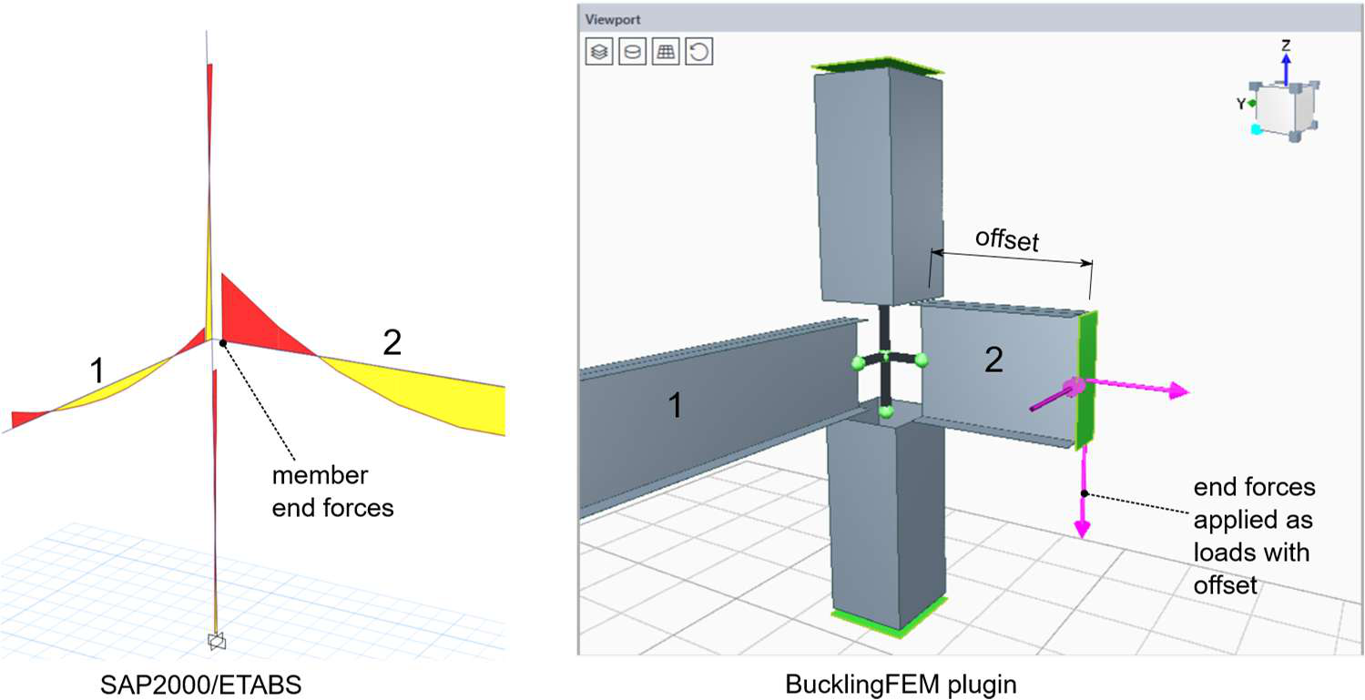
Loads and supports
The end forces are applied at the element ends, either manually or imported from an ETABS load case. The uniform loads are distributed along the element, with control over region, magnitude, position in the section, and eccentricity. The width acts only as a geometric filter: the total load does not depend on the number of shell elements involved.
The supports are defined in the element local coordinate system, with independent translations (U1, U2, U3) and rotations (R1, R2, R3). This is where engineering judgment is most critical: they must represent the behavior of the studied segment as part of the global system.
To reproduce a stress state, it is possible to import a full load case. A relevant detail is that forces applied to elements with End Length Offsets would generate a parasitic moment (transverse force × offset arm), which the program automatically corrects with an equal and opposite moment at the end. Self-weight is handled by the IncludeSelfWeight option, automatically activated when applicable.
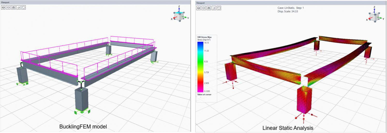
Analysis
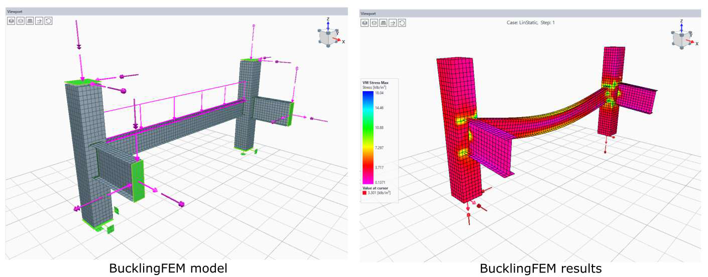
Calculations run on CSI’s SAPFire engine in the background. Mesh size is controlled by a single parameter, defined per element. Before the buckling study, a linear static analysis should be performed to validate connections, offsets, and loads, and to reveal stress concentrations that a frame model would never show.
The buckling mode analysis is the core of the plugin. It solves the generalized eigenvalue problem:
[ K − λ G(r) ] ψ = 0
where K is the elastic stiffness, G(r) the geometric stiffness due to loads, λ the buckling factors, and ψ the mode shapes. Each factor is the multiplier of the applied loads that would cause buckling: values above 1 indicate reserve, below 1 indicate instability, and negative values indicate buckling under load reversal.
Eigenvalue analysis itself is not exclusive to the module: any CSI software can perform it via a Buckling Load Case. The added value of BucklingFEM is that it avoids building shell-based submodels from scratch, automating discretization, connectivity, and load transfer, along with the other advantages described above.
Results and link to SAP2000
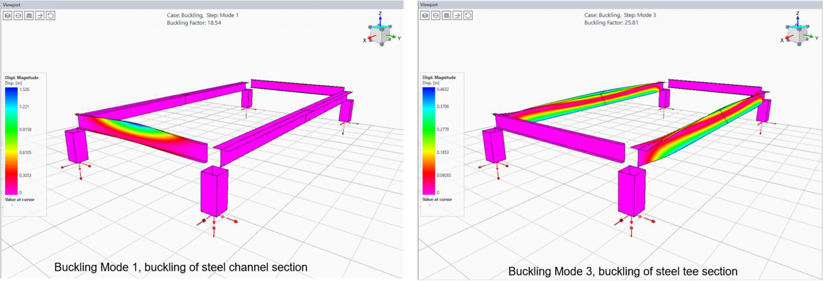
After the analysis, the program displays deformed shapes with adjustable scale, customizable contour plots, and interactive reactions. For buckling modes, the active step can be changed directly in the interface, and the factor is shown at the top of the viewport.
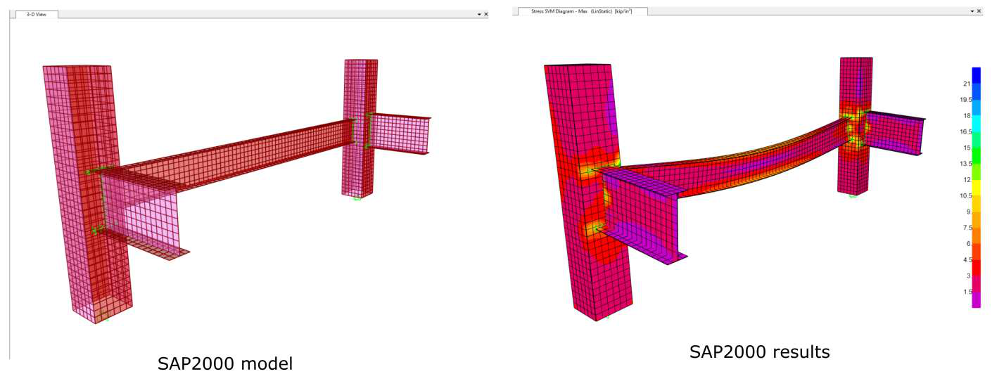
The most strategic feature is the direct export to SAP2000. With a single click, the full analytical model (geometry, properties, connectivity, and loads) is transferred: the plugin launches SAP2000, creates load cases, runs the analysis, and returns the results. This provides access to SAP2000’s advanced capabilities for more complex studies.
In summary
Currently available in ETABS, BucklingFEM does not replace code-based stability checks: it complements them with something they inherently cannot provide. A shell-based finite element view of local and coupled instability modes, obtained directly from an existing frame model. Future developments point toward geometric imperfections, material nonlinearity, and post-buckling response, some of which are already accessible through export to SAP2000. For engineers designing slender steel structures, it is the difference between trusting a formula and seeing the problem firsthand.