
Floor Cracking Nonlinear Analysis in ETABS / SAFE: Reinforcement Control for Cracked and Long-Term Stiffness
Accurately predicting deflections in reinforced concrete slabs requires understanding how ETABS/SAFE computes cracked stiffness. The Floor Cracking analysis automatically updates flexural stiffness element by element to reflect cracking and—when needed—longterm effects such as creep and shrinkage.
To obtain reliable results, engineers must know which reinforcement the analysis is actually using, how to control that reinforcement source in slabs and beams, and how to audit the outcome. Although the software does not yet provide a direct table listing the reinforcement used per finite element, it does allow reviewing the final flexural stiffness modifiers used in the last iteration of the Floor Cracking load case. These modifiers show exactly how cracked stiffness was ultimately distributed across the slab.
This article provides a clear, selfcontained workflow showing how reinforcement is selected, how to override it when needed, and how to verify the results confidently.
1) What this analysis does (and does not do)
1.1 How the cracked-stiffness interpolation works (visual reference)
The figure below illustrates the typical moment–curvature behavior of a reinforced slab member, showing the uncracked state (State 1), the cracking moment, and the fully cracked state (State 2). This diagram clarifies how the Floor Cracking algorithm transitions between stiffness states.
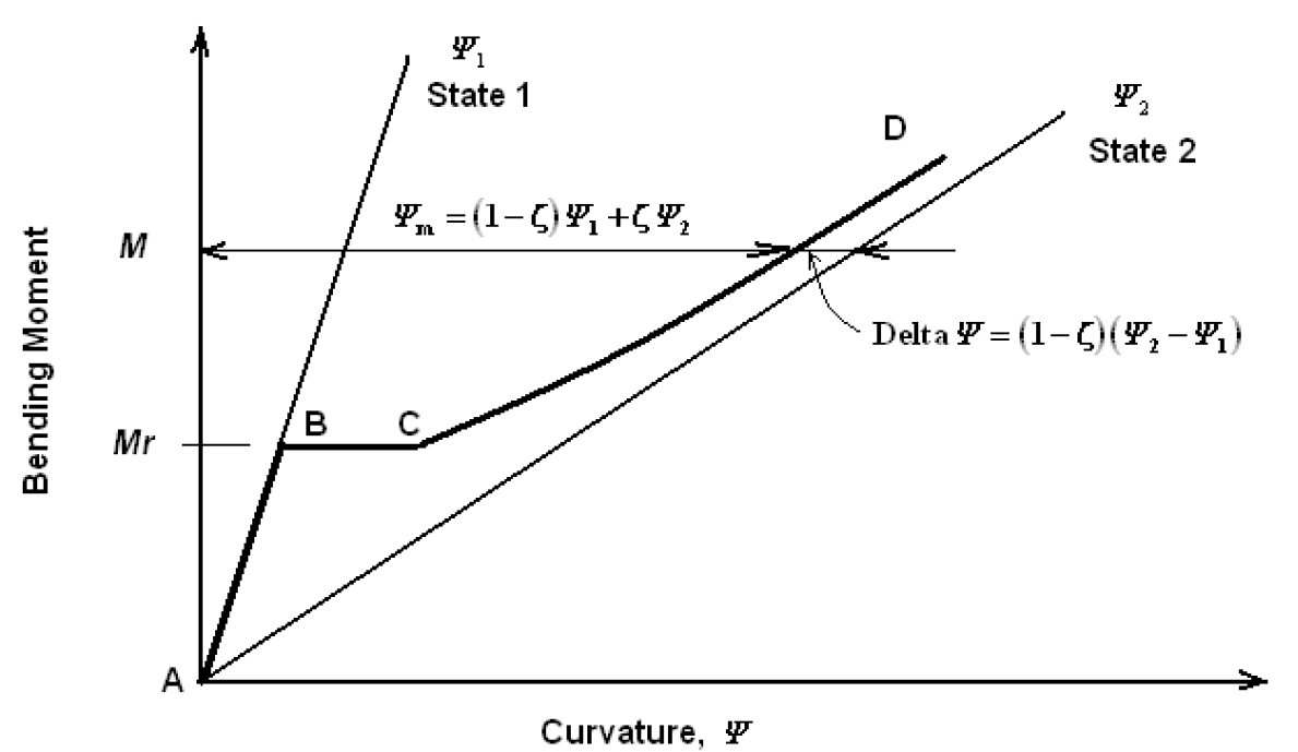
Moment versus curvature for a reinforced slab member.
1.2 What this analysis does
- Runs an iterative cracked-stiffness procedure.
- Uses a moment–curvature interpolation between uncracked and fully cracked states.
- Updates flexural stiffness modifiers per shell element and per bending direction.
- Includes creep and shrinkage effects in sustained loading for long-term cases.
1.3 What this analysis does not do
- This analysis does not model full materialnonlinear layered shell behavior in the slab’s inplane (membrane) directions.
- This analysis does not include nonlinear tensionstiffening, cracking, or softening effects in membrane behavior.
- This analysis does not replace detailed nonlinear layered shell modeling when the objective is to evaluate inplane restraint, shrinkageinduced membrane cracking, or nonlinear diaphragm action.
2) The control center: Analyze > Cracking Analysis Options
This form governs how reinforcement is taken into account for Floor Cracking and contains two key groups of settings.
2.1 Reinforcement Source (choose one)
- User-Specified Rebar / Designed Slab Rebar
- Where slab rebar objects exist (Draw > Draw Slab Rebar), they are used.
- Elsewhere, the routine uses designed slab reinforcement from the last slab design run.
- Quick Tension Rebar Specification
- Top Reinforcing and Bottom Reinforcing are uniform tension reinforcement specifications for cracking analysis (see Section 3.2 for an important nuance).
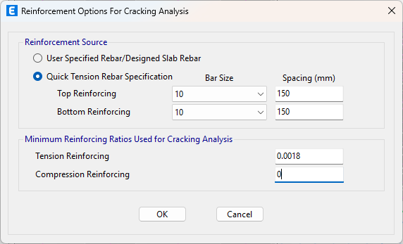
2.2 Minimum Reinforcement Ratios Used for Cracking Analysis
- Tension Reinforcing
- Compression Reinforcing
These minimum ratios are always enforced across the entire slab as a lower bound. Wherever the reinforcement implied by your Reinforcement Source is below these minimums, the minimums govern.
3) Slab reinforcement sources—what they imply
User-Specified Rebar / Designed Slab Rebar
- User slab rebar objects are analysis inputs for crackingrelated routines (they are not general detailing outputs).
- The priority in each region is:
- user-specified slab rebar (if drawn);
- otherwise, designed slab rebar;
- and minimum reinforcement ratios override both (1) and (2) wherever they are higher.
Older versions note: In some earlier releases, user slab rebar objects were not fully integrated into Floor Cracking. If you rely on user rebar in older versions, validate outcomes via the stiffnessmodifier audit in Section 6.
3.2 Quick Tension Rebar Specification (important nuance)
Quick does not create a constant top+bottom mesh. It adds reinforcement only where tension demand exists and does not place reinforcement in compression zones.
Practical consequence: Deflections are typically conservative compared with a real constant mesh, because Quick ignores the beneficial contribution of compression-zone reinforcement, especially for longterm (creep/shrinkage) behavior.
3.3 Modeling a constant base mesh correctly
If the slab truly has a constant top+bottom base mesh:
- Step 1 — Represent the base mesh via Minimum Reinforcement Ratios
- Set Tension Reinforcing and Compression Reinforcing minimums equal to the real base mesh. This enforces a uniform lower bound across the slab.
- Step 2 — Add local increases using slab rebar objects
- Where extra steel is needed (supports, openings, strips), draw the total reinforcement (base + extra) with slab rebar objects.
Do not draw only the extra: in regions with userspecified slab rebar, the program considers exactly what you draw (it does not add your extra to the minimums). Therefore, draw the full total reinforcement in reinforced zones.
4) Minimum reinforcement ratios—always active, sometimes governing
- Minimum ratios are always active as a lower bound.
- They govern only in regions where they exceed the selected source (user, design, or quick).
- Knowing where they govern is part of a good audit.
5) Beams — how reinforcement is used and how to control it
For beams, Floor Cracking typically uses longitudinal reinforcement from the Concrete Frame Design results. If those results exist, cracked stiffness for beams will reflect that designed reinforcement.
However, you may need to impose a constant reinforcement layout for stiffness purposes (e.g., realistic serviceability behavior, standardized detailing, or parametric studies). There are two practical routes:
5.1 The “Reinforcement Area Overwrites for Ductile Beams” trick
Within the beam section’s property data, you’ll find Reinforcement Area Overwrites for Ductile Beams.
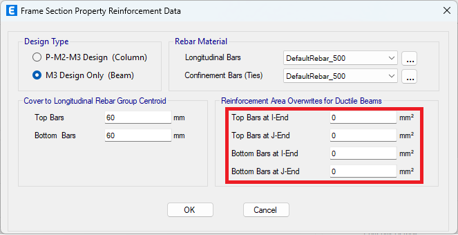
- These fields are intended for seismic ductility checks within Concrete Frame Design.
- Trick: If you specify reinforcement in these overwrite fields and ensure no available frame design results remain for those beams, the Floor Cracking routine will use the overwrite areas to define cracked stiffness.
Critical step: Clearing stored design results is not always enough. To reliably force ETABS/SAFE to drop the cached design reinforcement and use your overwrite values, reassign the beam section to the affected beams (even reassigning the same section). This rebuilds the design context so Floor Cracking reads the overwrite.
5.2 Convert beams to slab areas (shells) for full slab-style control
When you want full transparency and shellstyle control (e.g., wide beams, band beams, transfer regions):
- Use Edit > Edit Frames > Convert Beams to Slab Areas to transform the beams into shell strips.
- Then define reinforcement with slab rebar objects (drawing the total reinforcement where needed).
6) Auditing: use the final flexural stiffness modifiers (last iteration)
The program does not give a perelement table of “rebar used,” but it does provide the final bending stiffness modifiers per shell element and direction as of the last iteration of Floor Cracking.
Review these tabulated modifiers to understand how the slab stiffness was adjusted during the nonlinear iteration.
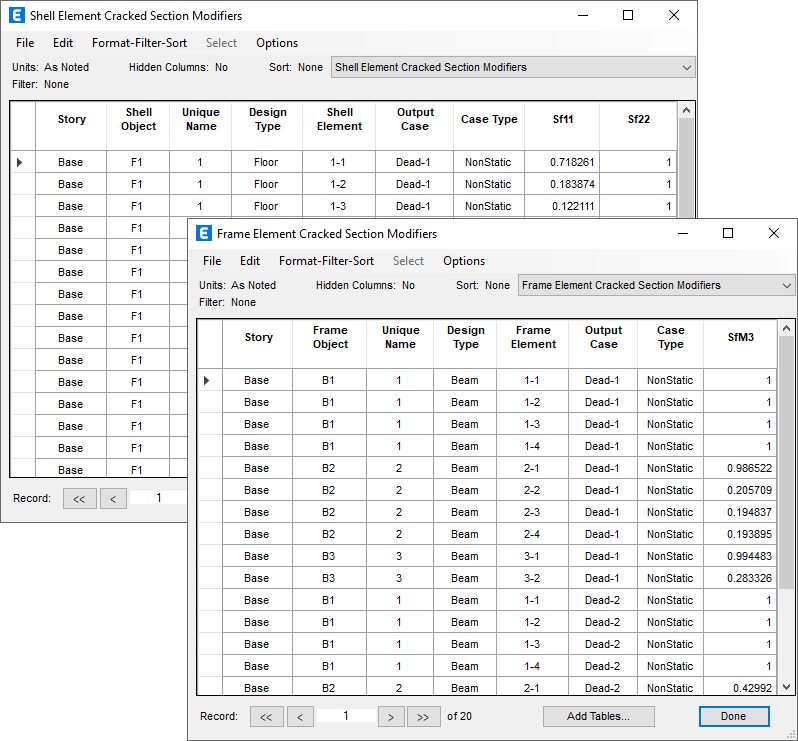
These modifiers are the tangible result of the cracked/longterm algorithm and show whether the model responded to your reinforcement assumptions.
Interpretation:
- Lower modifiers → more cracking / less stiffness
- Higher modifiers → less cracking / stiffer response
Use them to confirm that your base mesh, user rebar, minimums, or beam overwrites actually changed stiffness where expected.
Patterns should align with your expectations (midspan vs support, opening edges, locally reinforced zones, etc.).
7) Validation tests (quick and revealing)
- Minimum-ratio sensitivity
Increase the minimums slightly and rerun.
- If modifiers increase widely → minimums were governing there.
- If little changes → user/design reinforcement governed.
- Local patch test with user rebar
Draw heavier slab rebar in a small region and rerun.
- If modifiers increase locally → user rebar is being used.
- If no change → region governed by minimums or designed steel (or, in older versions, user rebar not fully integrated).
- Beam overwrite test
Change rebar overwrite noticeably and rerun.
- No change → stored frame design still governs.
- Reassign the beam section and retest.
8) Recommended workflow (slab + beams)
- Mesh the slab adequately for moment gradients.
- Define the Floor Cracking load case(s) (immediate and/or longterm).
- In Analyze > Cracking Analysis Options, set:
- Reinforcement Source
- Minimum Reinforcement Ratios (tension and compression)
- Slab control
- Base mesh via minimums; local increases via slab rebar objects, or
- Use designed slab rebar as primary; or
- Quick (only if appropriate—tensiononly, typically conservative by neglecting compressionzone contribution).
- Beams
- Use frame design reinforcement, or
- Use the ductile-beam overwrite trick + reassign section, or
- Convert beams to slab areas and control reinforcement via slab rebar objects.
- Run Floor Cracking.
- Audit the final bending modifiers per element/direction.
- Perform at least one validation test.
- Document what governed: minimums vs design vs user rebar; and confirm how beam reinforcement was imposed (design, overwrites+section reassignment, or shell conversion).
9) Video Demonstration
Watch the following video for an example of how this type of Floor Cracking analysis is applied. The ETABS models used in this video are attached.