
Link Elements in CSI software : Position of the Shear Spring
Local Coordinate System and Internal Deformations
Each Link/Support element has its own local coordinate system (axes 1, 2, and 3) used to define the force-deformation properties and interpret the results. The local axis 1 is the longitudinal axis, corresponding to axial deformation. Axes 2 and 3 are transverse axes, located in the plane perpendicular to axis 1, and correspond to shear deformation.
Six independent internal deformations are defined for the Link/Support element, calculated from the relative displacements between joint j and joint i (for elements with two joints) or between the joint and the support (for elements with a single joint).
All translations, rotations, and deformations are expressed in the element's local coordinate system. Shear deformation can be caused by both rotations and translations.
Position of the Shear Spring
A Link/Support Property defines the force-deformation relationship for the six internal deformations and can include mass and weight. Each Link/Support Property is considered a set of three translational "springs" and three rotational "springs," each associated with one of the six internal deformations.
Analyzing the position of the shear spring:
- The shear spring in the 1-2 plane is located at a distance dj2 from joint j.
- The shear spring in the 1-3 plane is located at a distance dj3 from joint j.
It is essential to understand the meaning of dj2 and dj3:
- dj2 represents the location where the shear deformation is measured.
- More importantly, dj2 is also the location where the bending moment due to the shear force is considered zero. This means that the position of the shear spring acts as a hinge for the bending moment associated with the shear force in that plane.
- Similarly, dj3 indicates the location where the shear deformation du3 is measured.
- And dj3 corresponds to the location where the bending moment due to the shear force is considered zero in the 1-3 plane.
It is assumed that all shear deformation in the 1-2 plane occurs at the shear spring located at dj2. The parts of the element that connect this spring to the joints (or the support) are considered rigid in shear. The force in the shear spring generates a bending moment that varies linearly along the length of the element. This bending moment due to the shear force is zero at the location of the shear spring (dj2 or dj3) and is independent of, and additive to, any constant bending moment in the element resulting from pure bending.
For an element that has a hinge in the 1-2 bending plane (i.e., whose stiffness to pure bending in that plane is zero), dj2 would correspond to the distance to that hinge.
By default, the distances dj2 and dj3 are zero, which means that the shear deformation is measured at joint j, and the bending moment due to the shear force is considered zero at joint j. The values of dj2 and dj3 can be different, although they are usually the same for most elements.
Understanding and correctly defining the values of dj2 and dj3 is essential for accurately modeling elements where the shear behavior is concentrated at a specific point, such as in certain types of connections in bridge abutments and piers, where a simplification in modeling the position of the shear spring can lead to completely different values from the actual situation.
Example of a Practical Case
The following images are intended to demonstrate the difference in results when using different values in the dj2 value.
The example applies to an I-beam simply supported at both ends. This first image represents the link applied at both ends, that is, it is a 2-joint link, which connects the centroid of the beam (joint j) to the base of the support at the abutment (joint i).
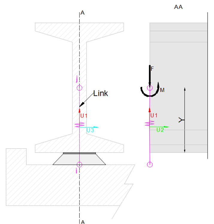

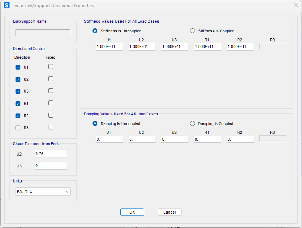
The applied Link is a link with linear behavior with the following degrees of freedom restricted. The second image is intended to illustrate the 3 springs in the 1-2 plane.

Below is the difference between using a dj2 equal to 0 meters, that is, coincident with joint j, and using a dj2 of 0.75 meters, which is equivalent to positioning the shear spring at the beam-support device interface.

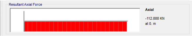
The image below shows the moments resulting from the application of a dj2 of 0 meters.


The image below shows the moments resulting from the application of a dj2 of 0.75 meters.

In Conclusion
The precise modeling of Link elements in CSI software (SAP2000, ETABS e CSiBridge) requires knowledge of their basic configuration, internal degrees of freedom, and the concept of internal springs. It is essential that users understand the position of the internal shear springs (dj2 and dj3), as these distances define where the shear deformation is assumed and, more importantly, where the bending moment due to the shear force is zero.