
Generalized Displacements in CSI Software
When performing structural analysis with CSI software, it is possible to define and use Generalized Displacements to more precisely evaluate critical deformations in a structure. This approach allows combining the displacements and rotations of multiple degrees of freedom in one or more joints, leading to a single parameter that represents global movements of interest to the project.
Definition and Purpose
A Generalized Displacement is a user-defined displacement that gathers deformations at key points in the model. Practically, it consists of a linear sum of translations and rotations in various degrees of freedom, scaled as needed. For example, one can measure the difference in horizontal displacement between two stories by applying a factor of +1.0 for the upper story’s degree of freedom and −1.0 for the lower story’s degree of freedom.
- Translational: The resulting value is in units of length. The scale factors associated with translations are dimensionless, while for rotations, lengths are applied. For instance, to evaluate a point translation on a rigid lever based on the rotation around its pivot, you multiply that rotation by the distance from the pivot to the point. In that case, that distance is entered as the scale factor for the joint rotation.
- Rotational: The resulting value is reported in radians (dimensionless). In this scenario, the coefficients applied to translations are the inverse of the length, while those applied to rotations are dimensionless. For example, to evaluate the rotation of a rigid lever using two translations, you can divide the difference in displacements by the distance between those two joints. In that case, the scale factor for one of the displacements would be -1/L, and for the other, +1/L.
Generalized Displacements can also be used to monitor nonlinear static analyses or optimization goals (CSiLoadOptimizer) in the SAP2000 environment.
Creating Generalized Displacements in SAP2000
- Tool Access: Select “Define > Generalized Displacements” from the main menu.
- Naming: Assign a name to the Generalized Displacement (e.g., GDISP1).
- Type Selection: Choose between Translational or Rotational, depending on the analysis goal.
- Joints and Scale Factors: Associate the relevant joints (joint IDs), specifying the degree of freedom (U1, U2, U3, R1, R2, R3) and the “weight” each one contributes to the calculation. Positive values are added, and negative values are subtracted.
Practical Example
Suppose you want to measure the relative displacement in the X direction between two stories of a building. You can create a Generalized Displacement (DRIFT2), selecting a pair of joints at the location where you wish to measure this displacement:
- Joint 9 on Story 2: factor +1.0 in U1
- Joint 12 on Story 1: factor −1.0 in U1
(considering that the joints’ local axes have the default orientation: U1 = UX)

In this way, whenever SAP2000 presents results for static or dynamic analyses, you can directly read the “DRIFT2” value in the output tables, corresponding to the X displacement difference between these two stories.
Applicability in Response Spectrum Analyses
When modal analyses using a Response Spectrum are carried out to design a building under seismic loads, the modes are combined through procedures such as CQC (Complete Quadratic Combination) or SRSS (Square Root of the Sum of the Squares). In these cases, it is important to note:
- The modal combination is performed after calculating the value of the Generalized Displacement for each mode. That is, the displacement is obtained for each vibration mode first, and then all modes are combined.
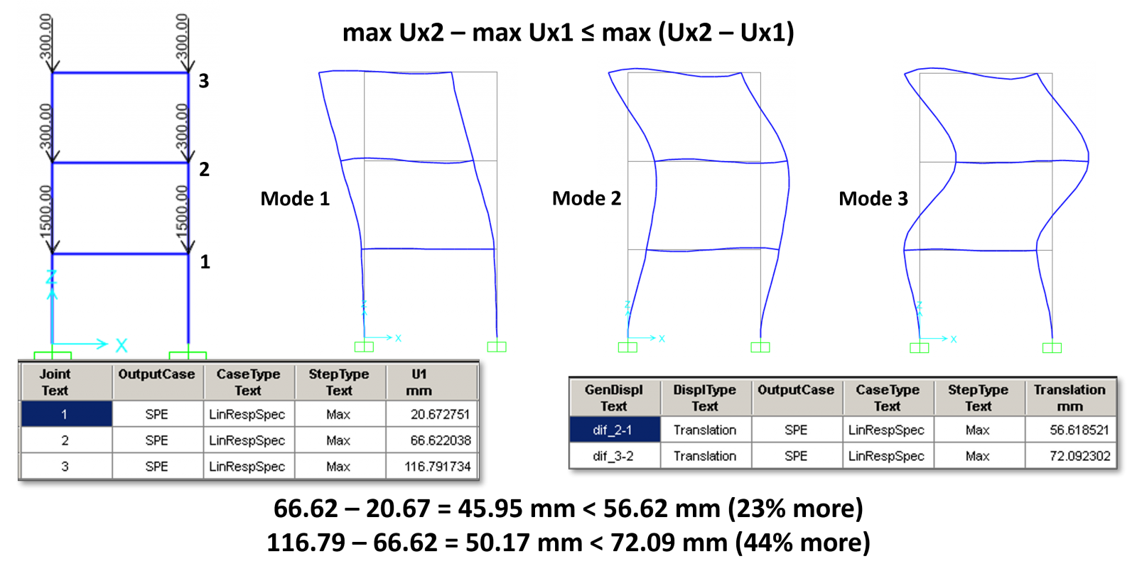
- Consequently, the displacement difference between two joints—obtained through Generalized Displacements—is not just the subtraction of each joint’s “maximum” responses. Instead, the software yields combined effects that may be significantly larger than a simplistic subtraction of absolute maximums.
A straightforward example is defining a Generalized Displacement to measure the difference in Ux translation between two joints, one on the lower story and the other on the upper story. Even if the lower joint experiences a maximum displacement “Ux1” of 21 mm and the upper joint a maximum “Ux2” of 67 mm, it is not necessarily correct to assume that the maximum difference is 46 mm. This occurs because each mode is evaluated independently before quadratic summation or the CQC combination. In practice, the maximum difference will always be greater than 46 mm.
In conclusion, simply obtaining the spectral maximum displacements of a building does not suffice to accurately calculate the relative displacements between stories. However, using Generalized Displacements makes it straightforward to compute these results. Note that the drifts automatically calculated by ETABS rely precisely on this CSI software functionality. Similarly, the TOWERS plugin (for SAP2000) also uses Generalized Displacements to calculate the relative displacements between stories.
Use in Nonlinear Analyses
In addition to the above-mentioned benefit of obtaining relevant results, Generalized Displacements may also be used to monitor displacement-controlled nonlinear static analyses.

Conclusion
Generalized Displacements is a powerful tool for anyone needing to clearly analyze specific deformation and relative displacement patterns in a structure. By combining displacements from multiple degrees of freedom into a single parameter, they enable automated, simplified checks and facilitate plotting force-deformation or moment-rotation diagrams, among other uses.