Modeling Steel Components with Gaps and Contact in SAP2000: Practical Approach Using Shell Elements
This article presents the methodology used to model complex steel components with gaps, contact, and nonlinear behavior in SAP2000, inspired by the excellent work developed by engineer Carlos Gustavo Lorente Elvira for the company TECOZAM in the “Sotra Bridge” project (Norway). The objective is to provide a practical, simple, and direct guide, accompanied by illustrative images.
1. Introduction
Special steel components, with welded plates, stiffeners, localized contact areas, and real gaps between bolts and holes, require modeling techniques that go beyond simple geometric discretization using finite elements. In this article, we show how to effectively leverage Shell elements, combined with links, frames, joint offsets, area springs, and constraints, to reproduce the structural behavior with the required level of rigor.
.png)
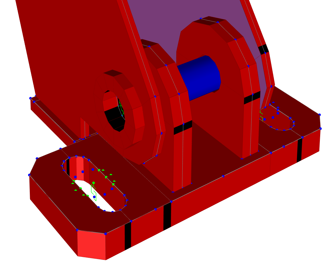
2. Joint Offsets: Realistic Representation of Eccentricities
The Joint Offsets allow shifting the joints of the elements, simulating thicknesses, eccentricities, and the correct continuity of the vertical plates up to the face of the base and top plates (and not up to their geometric axis).
This is especially useful in welded plates with stiffeners, ensuring that the model reflects the real geometry without creating unnecessary discontinuities in the finite element mesh.
.png)
3. Area Springs to Simulate Contact with Concrete
The Area Springs allow defining distributed springs that work only in compression, representing the contact between the plate and the supporting concrete.
- SAP2000 automatically distributes these springs among the mesh joints.
- The user can control their direction, stiffness, and type of behavior (compression-only).
If it is necessary to consider plate–concrete friction, it is also possible to use area springs based on links with Friction Isolator behavior. For this purpose, we recommend consulting Exercise 28 of the Advanced SAP2000 Course
.png)
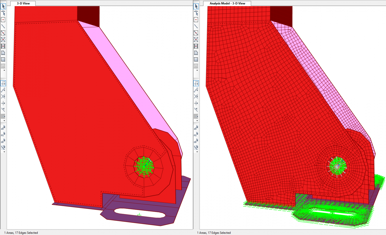
4. Auto-Mesh and Mesh Compatibility
To facilitate modeling and editing:
- Use few area objects (when possible, a single area per plate).
- Allow SAP2000 to generate the mesh automatically (Auto-Mesh).
- Ensure mesh compatibility only at the necessary points.
- When meshes do not match, use Edge Constraints to ensure displacement compatibility between panels.
Recommended article: Edge Constraints in SAP2000
5. PLATE-Type Joint Constraints for Base Plate Bolts
To simulate the rigid contact between the bolt head and the base plate, Plate Constraints are used, which impose displacement compatibility and allow the plate to rotate over the bolt in a coherent manner.
More information in Section 1.2.6 of the Advanced SAP2000 Course
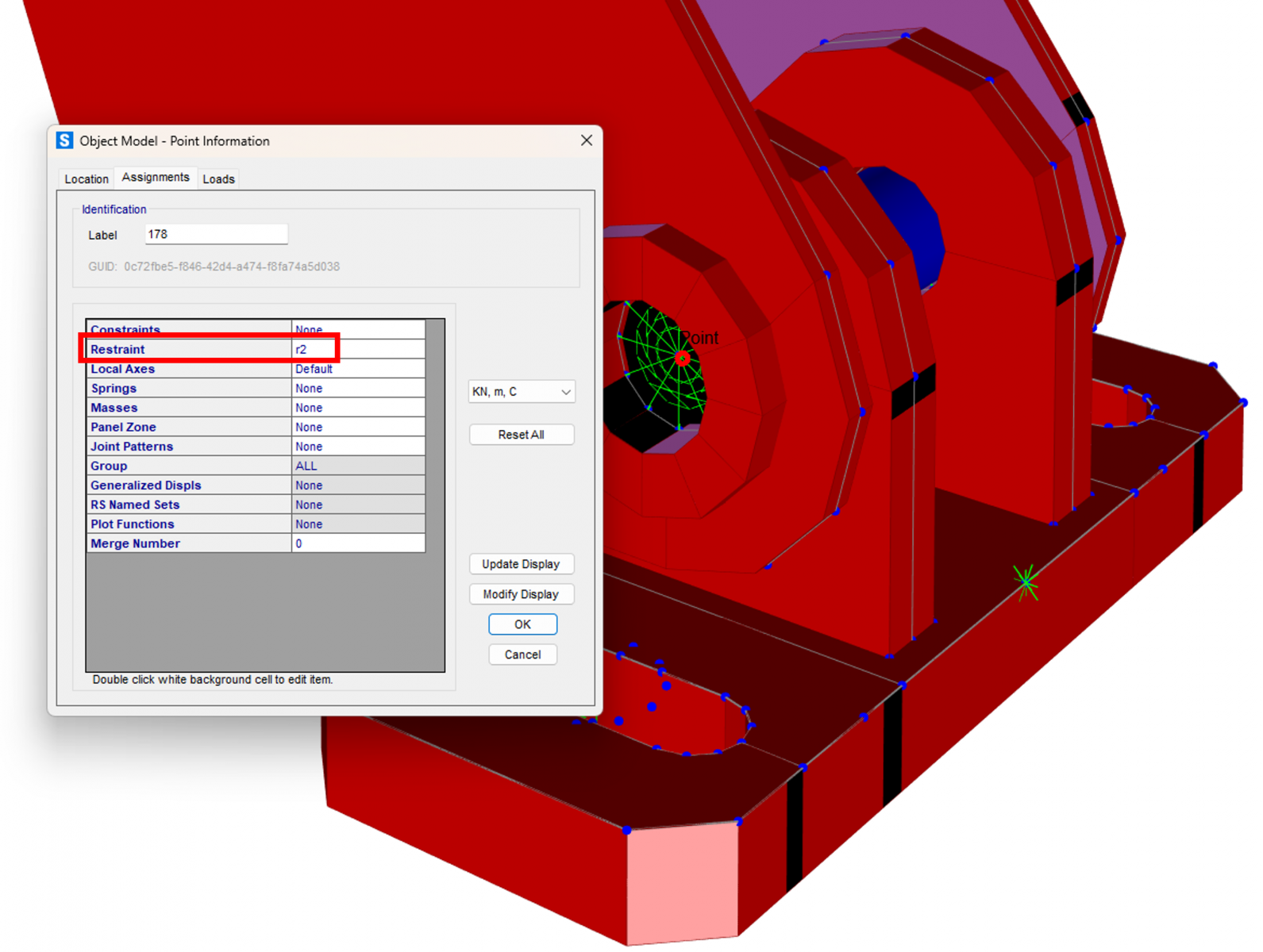
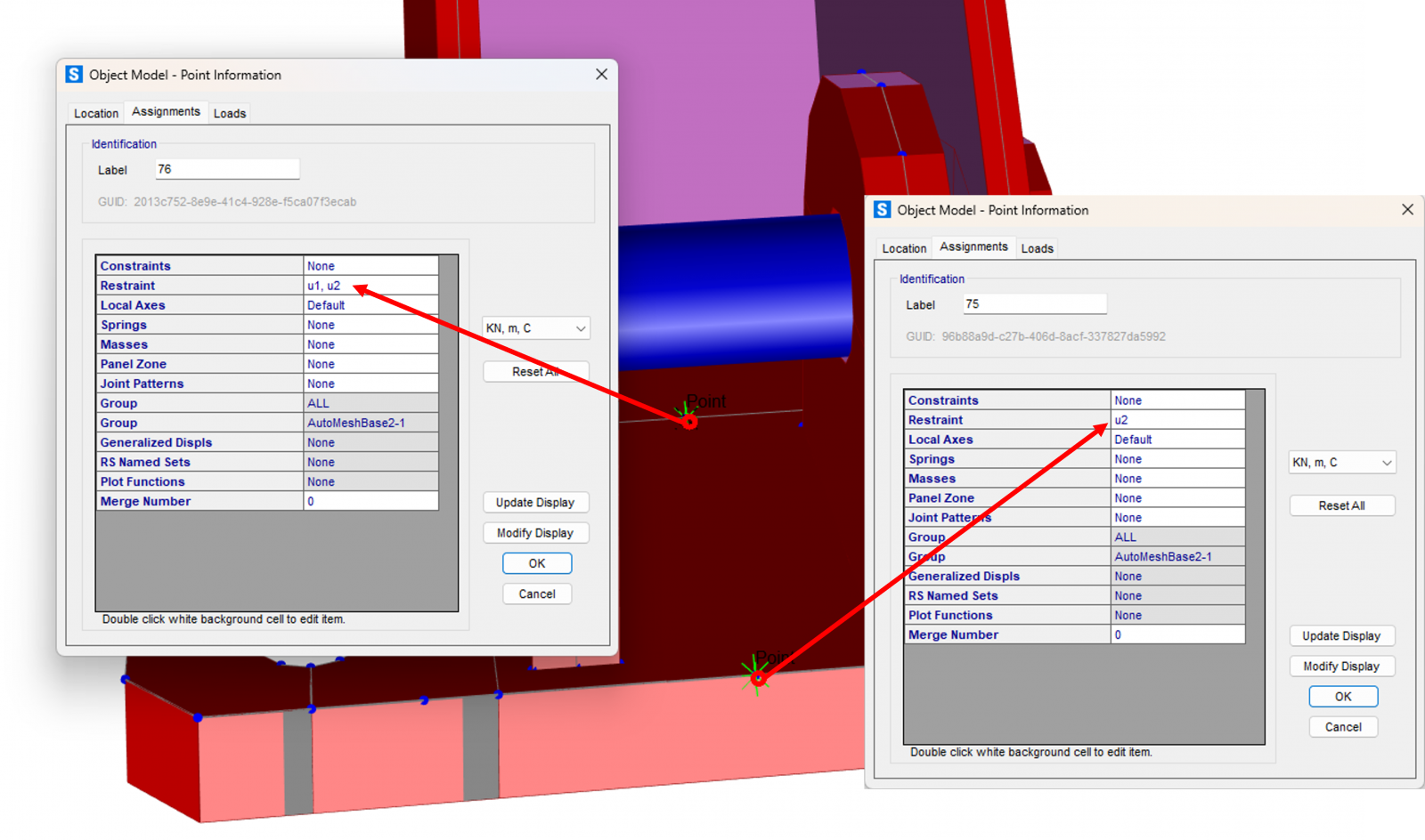
6. Minimum Constraints for Global Model Stability
To avoid free degrees of freedom and ensure stability in a model with contacts and high stiffness:
a) Block the RY rotation along the bolt axis to avoid instabilities in the four contact joints:
b) Laterally restrain the base plate in an isostatic manner:
- one joint with UX + UY restrained
- another joint with UY restrained
It is recommended to apply these restraints outside the direct contact zone to avoid artificial stiffness.
The bolt is modeled as a frame, assigning it a very low axial modifier (for example, EA × 1e‑6 through Property Modifiers) to eliminate axial interaction with the holes. This allows simulating perfect sliding while retaining only the desired bending and shear effects.
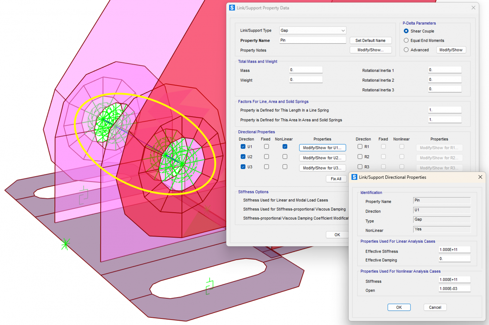
8. Radial GAP Links (1 mm Clearance) for Bolt–Hole Contact
- Radial GAP 2 Joint Links with 1 mm clearance are used, representing the real contact between the bolt and the hole.
- It is necessary to assign very low shear stiffness to the springs at joint j (the ones connected to the plate) to avoid numerical instabilities.
Recommended article: Link Elements in CSI software : Position of the Shear Spring
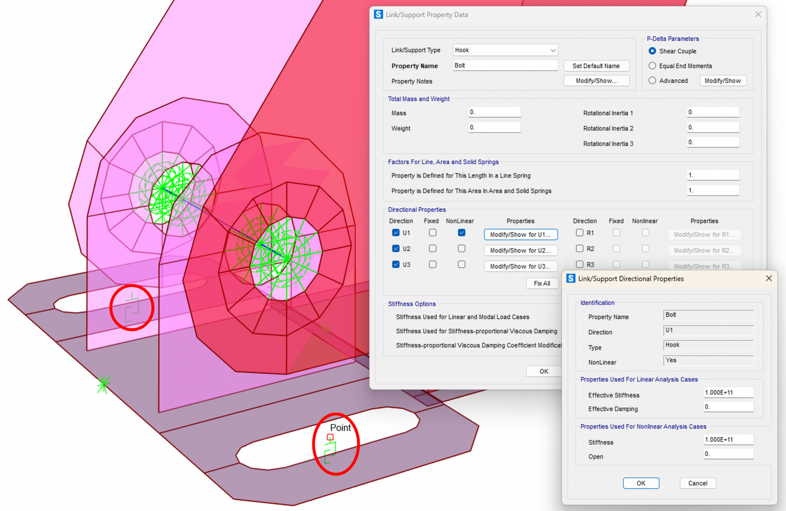
9. Modeling the Base Plate Bolts
For each vertical bolt:
- a 1 Joint Link is used
- with Hook behavior in the vertical direction
- and rigid springs in the horizontal directions, but not defined as “Fixed”, since these joints will be connected to Plate Constraints to better represent the contact between the bolt head and the plate
Recommended article: Correct definition of constraints in SAP2000
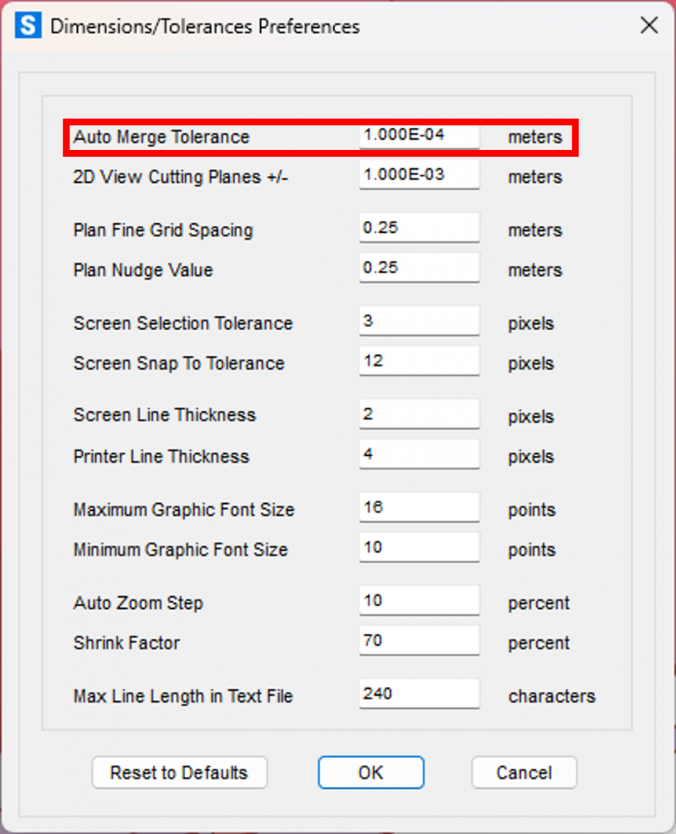
10. Auto Merge Tolerance: Essential Adjustment in Small Models
Due to the small size of the elements, define:
- Auto Merge Tolerance = 0.1 mm
The default value (1 mm) could cause undesired joint merging during automatic mesh generation.
11. Considerations on Plasticity and Geometric Nonlinearity
- In this case, the client only wanted to verify that the stresses in the plates did not exceed yield.
- If plasticity needed to be modeled, SAP2000 allows considering material nonlinearity in Shell elements using the von Mises criterion.
- The studied components were not slender, so geometric nonlinearity was not considered.
- Even so, when necessary, it is simple to define geometric imperfections and activate geometric nonlinearity in the analyses, including large displacements.
For those interested in exploring this topic further, we recommend the course: Geometric Nonlinearity
Excerpt from an exercise in the course where these concepts are applied in a post‑buckling analysis of the web of a steel girder:
12. Next articles
This article will be part of a series dedicated to:
- modeling complex steel components
- different contact approaches
- modeling with 3D solids
- advanced phenomena such as multiple gaps, friction, localized yielding, etc.
The SAP2000 models used will be available for download, including the model presented in this article.
Conclusion
Modeling steel components with gaps and contact in SAP2000, when done rigorously, makes it possible to reproduce real behavior with sufficient confidence without the need to resort to excessively heavy solid models. The proper use of joint offsets, area springs, links, constraints, and controlled meshes provides an optimal balance between realism and computational efficiency.