
Advanced Modeling in SAP2000: Generating Shells from Frame Objects
In the modeling of complex structures, such as barrel vault roofs or double curvature surfaces, the structural engineer frequently faces the challenge of efficiently defining the surface geometry (Shell elements).
Often, the base geometry is defined through a "skeleton" of frame objects. Transitioning from this skeleton to a continuous surface of finite area elements can be laborious if done manually. SAP2000 offers two powerful tools in the Edit > Extrude menu to automate this process.
Although the final result appears identical, the mathematical and operational logic of each command is fundamentally distinct. In this article, we analyze the differences between Extrude Lines to Areas and Add Areas between Lines.
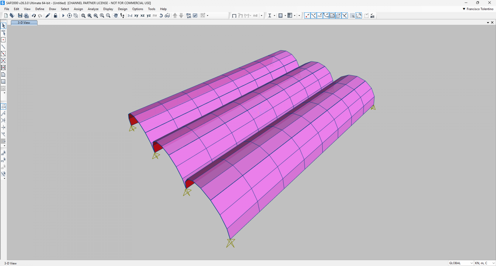
The Test Scenario: Barrel Vault
Imagine you have modeled a series of parallel arches using frame objects to simulate a barrel vault. The goal is to create the roof surface by connecting these arches.
1. Extrude Lines to Areas: The Sweep Concept
The Extrude Lines to Areas command is based on the concept of "sweeping" or classic extrusion. The logic here is the generation of new geometry through the projection of an existing object into space.
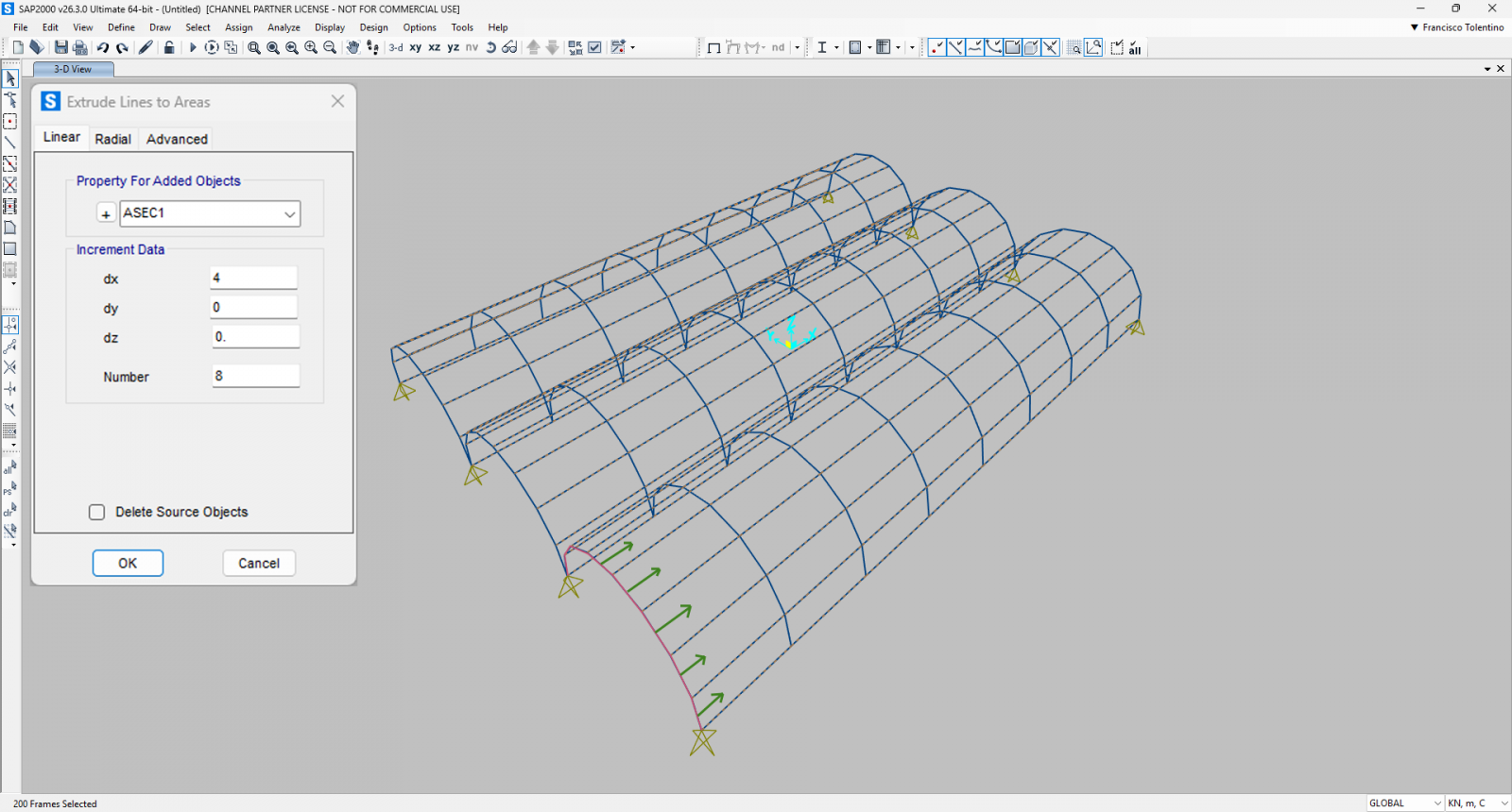
- The Logic: The program takes a selected frame object and "drags" it in a defined direction (Linear) or rotates it around an axis (Radial). The trail left by this movement transforms into the Shell element.
- Application: It is ideal when you only have the generating profile (for example, a single initial arch) and intend to generate the entire tunnel of the vault.
- Parameters: It requires the definition of precise mathematical increments dx, dy, dz (for linear; or angle and axis for radial).
Technical Note: This command increases the object's dimension by one degree. A point (dimensionless) extrudes to a line (1D); a line (1D) extrudes to an area (2D).
2. Add Areas between Lines: The Interpolation (Loft) Concept
The Add Areas between Lines command operates under a completely distinct topological logic. It is not about projecting geometry into the void, but rather filling spaces between existing geometry.
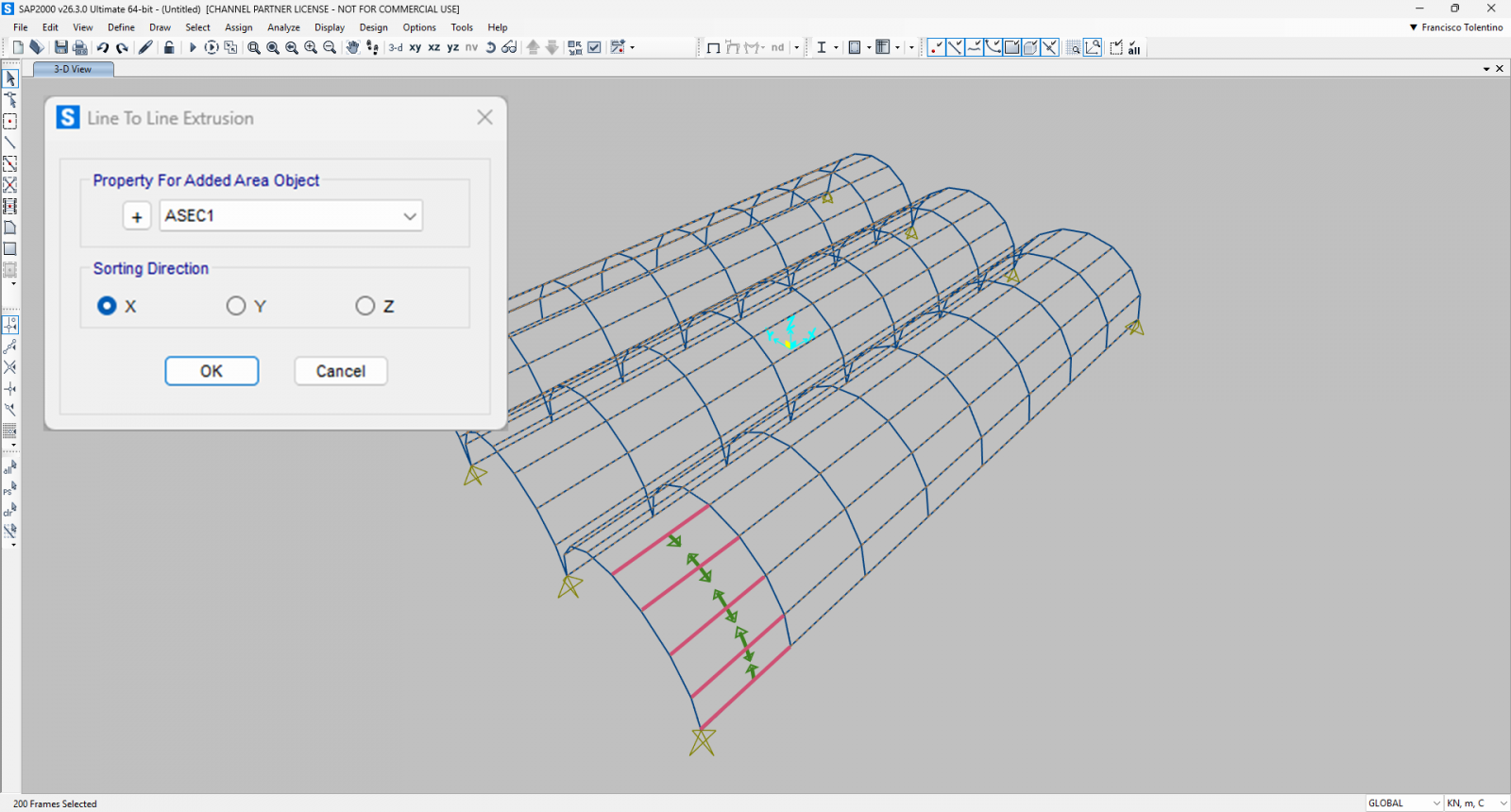
- The Logic: The user selects multiple adjacent frame objects. The SAP2000 algorithm sorts these lines based on a sorting direction and generates Shell elements to close the space between them.
- Application: This is the perfect choice for our vault example where all the arches are already modeled. Instead of creating new geometry based on increments, the command uses the existing joints of the frames as vertices for the new Shells.
- Tolerance to Distortions: A critical advantage of this command, often unknown to users, is its ability to handle imperfections. It allows for the creation of Shells even if the four resulting joints are not perfectly coplanar (within a certain tolerance), or if the frames are not perfectly parallel, generating slightly distorted elements that adapt to the structure's "free form."