
Tension and Compression Limits in Frame Elements
For seasoned structural engineers using advanced analysis tools like SAP2000, ETABS, or CSI Bridge, accurately modeling the real-world behavior of components is paramount. One powerful yet simple features for this purpose is the Tension/Compression Limits assignment for frame elements. This nonlinear property allows engineers to effectively model elements that have different capacities in tension and compression, such as slender braces that buckle, cables that cannot take compression, or foundation elements with uplift.
This article provides a deep dive into the Tension/Compression Limits feature, demonstrating its application through a practical example of a transmission tower to show how it can refine your structural models for more realistic results.
Understanding the Mechanics of Tension/Compression Limits
At its core, the Tension/Compression Limit is a nonlinear, elastic property assigned to a frame object. When you define a limit, you are telling the software that the element can only sustain a certain amount of axial force.
- Elastic Behavior: If an element reaches its compression limit, for instance, it will continue to shorten without accumulating any additional stress (i.e., with zero axial stiffness). However, this deformation is fully recoverable. If the load reverses, the element will regain its original length at zero stiffness before re-engaging its full axial stiffness to resist tension.
- Nonlinear Analysis is Key: This feature is only activated during nonlinear static or nonlinear direct-integration time-history analyses. Linear analyses do not recognize these limits and will use the element's full axial stiffness (AE/L), regardless of the assigned limits.
How to Assign Tension/Compression Limits
Applying these limits in any CSI software is a straightforward process:
- Select the Elements: In your model, select the frame object(s) you wish to modify. These would typically be your braces, cables, or other elements intended as tension-only or compression-only.
- Navigate to the Menu: Go to the Assign menu > Frame > Tension/Compression Limits.
- Define the Limits: The "Frame T/C Limits" form will appear with the following options:
- Tension Limit: Check this box to define a maximum tensile force. The value must be zero or positive.
- Compression Limit: Check this box to define a maximum compressive force. The value must be zero or negative. A value of 0 is commonly used to create a "tension-only" member.
Note: If you set both the tension and compression limits to zero, the element will be unable to carry any axial force in a nonlinear analysis, effectively acting as a placeholder element.
Practical Example: Modeling a Transmission Tower
Let's illustrate the power of this feature with a common structural scenario: a transmission tower with slender diagonal braces subjected to lateral wind loads. These braces are highly effective in tension but are assumed to buckle and provide negligible resistance when subjected to compression.
Step 1: Initial Linear Analysis
First, we model the transmission tower and run a standard linear static analysis under a lateral load case. When we review the axial forces in the diagonal "X" bracing, we get a result like the one shown below.

As expected, the linear analysis, using the full stiffness of all elements, reports significant compressive forces in the diagonals leaning into the load and tensile forces in the opposing diagonals. This is not a realistic representation of the structure's behavior, as the slender braces would buckle long before developing such high compressive forces.
Step 2: Applying the Compression Limit
To correct this, we will model the braces as tension-only elements.
- Select all diagonal brace elements in the tower model.
- Navigate to Assign > Frame > Tension/Compression Limits.
- In the form, check the Compression Limit box and enter a value of 0. This tells the software that these selected elements cannot resist any compressive force.
- Click OK.

Step 3: Running a Nonlinear Analysis
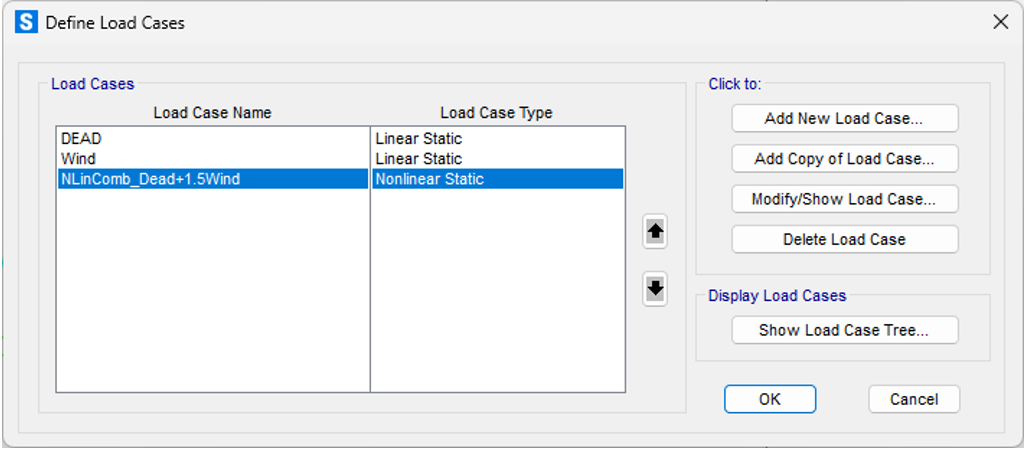
With the compression limit assigned, the next crucial step is to run a nonlinear static analysis. A linear analysis would ignore our new rule. By converting the linear wind load case to a nonlinear one (often as simple as changing the case type in the "Define Load Cases" menu), we allow the software to account for the tension-only behavior.
Step 4: Reviewing the Realistic Results
After running the nonlinear analysis, we examine the axial force diagram for the same lateral load.
The results are dramatically different and far more realistic:
- No Compression: The diagonal elements that were previously showing high compression now report an axial force of zero. The software correctly identified that these elements tried to go into compression, and per our rule, their stiffness was removed, preventing them from taking on load.
- Load Redistribution: The tensile forces in the active (tension-only) diagonals have increased. The structure has automatically redistributed the lateral shear to the elements that are capable of resisting it, providing a more accurate picture of the load path.

Conclusion and Key Takeaways
The Tension/Compression Limits feature is an indispensable tool for experienced engineers seeking to create more accurate and efficient structural models in SAP2000, ETABS, and CSI Bridge. By understanding its nonlinear nature and applying it correctly, you can easily simulate the behavior of tension-only or compression-only systems without resorting to more complex and computationally expensive analysis types.
Remember these key points:
- Always Use a Nonlinear Analysis: Limits are ignored in linear static analyses.
- It's an Effect-Based Tool: This feature is perfect for modeling the effect of a tension-only member on the overall structure. For detailed studies on the buckling behavior of a brace itself, a more granular approach is needed, such as subdividing the element and running a P-Delta large-displacement analysis.
- Improves Accuracy: Using this feature prevents the overestimation of stiffness and provides a more realistic view of force distribution in structures with elements like slender braces or cables.