
Best Practice for Rigid Connections in CSI Programs: High Stiffness vs Fixed Links
When defining rigid links, users have the chance to choose between Fixed behavior or to assign sufficiently large stiffness values. This article explains why the latter approach is generally recommended, particularly when staged construction is needed. Some topics were also covered on Best Practices for defining Restraints and Constraints in SAP2000 Structural Models.
Importance for Analysis
A link element with a "Fixed" degree of freedom essentially implies that the deformation for that specific DOF is zero. For a two-joint link, this is equivalent to specifying a joint constraint; for a one-joint link, it behaves like a support restraint. While seemingly straightforward, this "Fixed Behavior" option comes with significant limitations:
- Computational Issues and Accuracy: It is not recommended to directly connect links with fixed DOF to other objects that also have fixed DOF, or to joints already under a constraint condition. Doing so can lead to multiply-constrained joints, which may result in inaccurate dynamic analysis results. Moreover, including a given DOF in multiple constraints is also generally not recommended, as the analysis might struggle to combine them accurately, especially for dynamic scenarios.
- Forces Output: A critical limitation of fixed DOF is that link forces are not reported for these fixed directions. This can hinder the comprehensive review and understanding of structural behavior, as forces acting along these supposedly rigid connections will remain unrevealed.
- Loss of Mass Coupling: For non-zero length links, fixing fewer than all six DOF can lead to a loss of mass coupling between rotational and translational DOF, which can affect the dynamics of the structure, especially when large masses or rotational inertias are present at the connected joints.
- Staged Construction: “Fixed” link DOFs are not affected by Change Section operations; these restraints/constraints remain fully enforced and their stiffness cannot be changed within that stage.
As an alternative, it is strongly recommended to use sufficiently large stiffness values to represent rigid conditions. These values should be large enough to prevent significant deformation but not so excessively large as to cause numerical sensitivity during the equation solution, particularly near nonlinearities in the model. A general guideline is to select stiffness values that are approximately 100 to 10,000 times larger than the corresponding stiffnesses in any connected elements that are expected to undergo deformation. For instance, values on the order of 1e11 kN-m (or kN-m/rad) are suggested for concrete structures.
Practical Example
A practical example with images illustrating the application of high stiffness values in link elements for rigid connections and staged construction scenarios are presented below.
Stage 1: Foundation Structure, Bottom Links and structure are added to the model including loads.


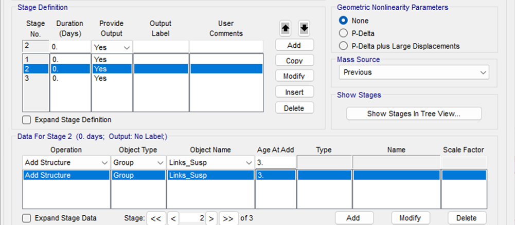
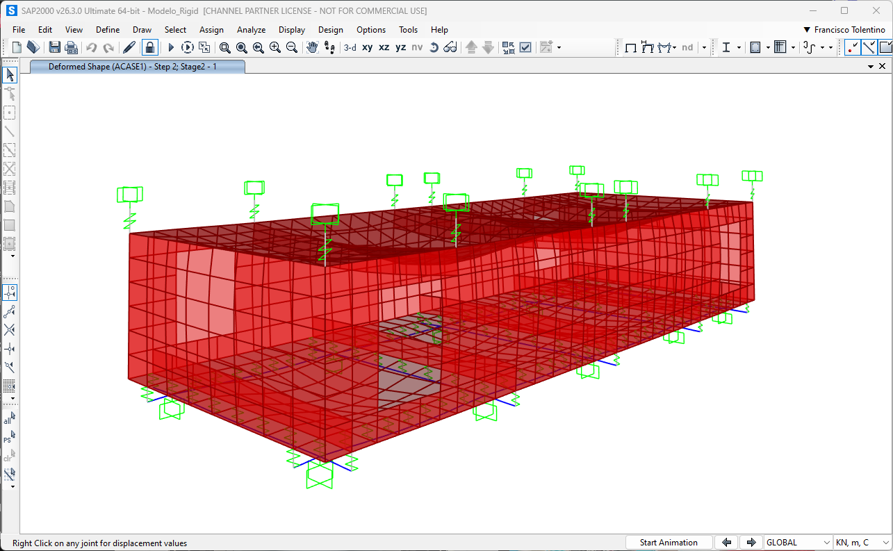
Stage 2: The top suspension links (Links_Susp) are activated in the model. However, since no loads were added to this stage, structural displacements and stresses remained unchanged.
.png)
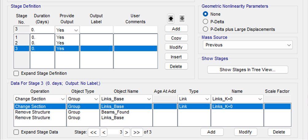
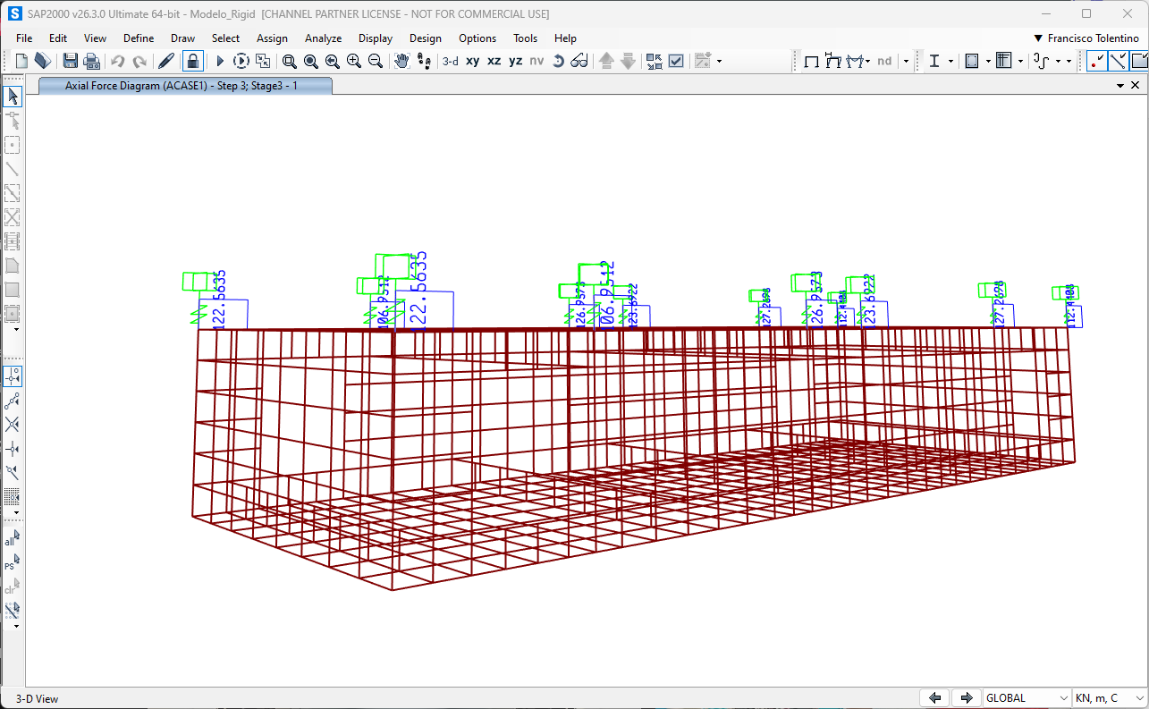
Stage 3: The final construction stage involved the removal of the foundation structure and Change Section Operation on Bottom Links. As a result, the entire structural loads were transferred to the suspension links.

Now, for a challenge: Try replicating this example on your own, but this time, define the connections using 'Fixed' links. Compare your results and see how structural behavior changes.