
Insertion Points: Impact on Structural Behavior
The concept of Insertion Point is a crucial aspect of structural modeling in software like those developed by Computers and Structures, Inc. (CSI), including SAP2000, ETABS, CSiBridge, and others. It defines the relationship between the physical position of a structural member (like a beam or column or even a shell) and the analytical line or point that represents it in the computational model. This article will focus on beam elements.
Understanding Insertion Points
By default, prismatic objects are positioned so that their centroid aligns with the analytical line drawn in the model. However, specifying an insertion point allows you to offset the object's physical position relative to this analytical line.
Example: If you need to model a beam so that its joints (the analytical joints) are at the top flange, you will assign a top-center insertion point. This action positions the girder physically below the line representing its analytical location. This offset is fundamental for accurately representing the physical geometry and its interaction with the rest of the structure.
Impact on Structural Response and Beam Reactions
The location of the insertion point has a significant impact on the analytical response of the model, particularly affecting beam reactions and the generation of longitudinal forces.
- Generation of Internal Constraints and Longitudinal Forces:
Standard modeling procedures typically assume object boundary conditions are located along the centroid of the cross-section.
However, when a simply supported (pin-pin) frame object is modeled with a top-center or bottom-center insertion point, internal constraints are generated which have the effect of a vertical offset.
A kinematic result of this modeling technique is the generation of longitudinal forces which act on an arm about the neutral axis. This means that forces that would normally pass through the centroid are now acting eccentrically, creating secondary effects. This behavior can be observed in real-world scenarios, such as when bridge girders are supported by bearing links located at their bottom.
- Impact on Deflection and Moments – A Detailed Example:
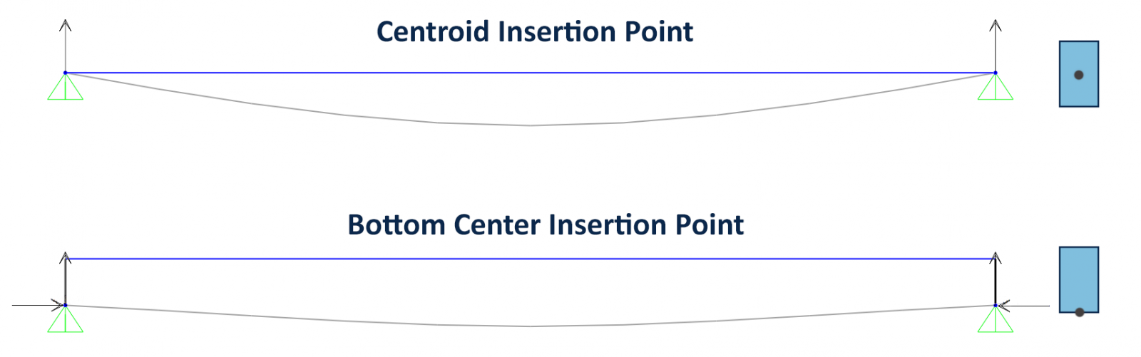
Consider a simply supported beam with pin supports at both ends, subjected to a gravity load.
Case 1: Default insertion points at the object centroid (standard modeling).
Case 2: Bottom-center insertion point (offset modeling).
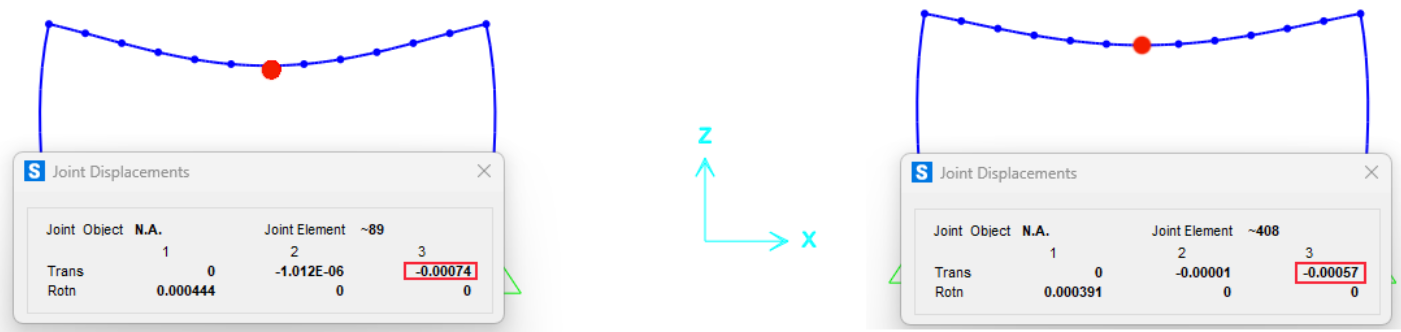
Upon analysis, the midspan deflection for Case 1 is larger than for Case 2. Although the beam stiffness is identical in both cases, this discrepancy arises from the difference in boundary conditions caused by the variable insertion-point location.
In Case 2, the longitudinal restraint (from the pinned supports) is at the Bottom-Center insertion point, not the centroid. This offset prevents the bottom fibers of the beam from elongating, which would normally occur under flexural loading. As a consequence:
- A longitudinal Compression force is introduced.
- This force acts on an arm about the neutral axis, creating a negative moment.
- This negative moment counteracts and reduces the positive moment from the applied vertical loading.
- The net effect is a reduction in the midspan displacement.
Mitigating Undesired Effects
If the generation of these longitudinal forces and associated eccentric moments is not desired for a particular analysis, one of the pin supports can be changed to a roller support condition. Introducing a roller support would release the beam from this longitudinal response, thereby eliminating the longitudinal forces and their eccentric moments. This modification is crucial when these secondary effects are not intended to be part of the primary analysis, or when simpler, non-offset behavior is desired.
Examples
- Centroid Insertion Point
Below, we can see the moments for a simply supported beam with the Centroid as the Insertion Point. The exact same stresses are expected for both beams.

- Top Center Insertion Point
Now, we can see moments for a simply supported beam with a Top Center insertion point. Different stresses are expected in the two beams due to hyperstatic reactions in the right beam, which introduces the secondary moments discussed earlier.

- Bottom Center Insertion Point
Similarly, for a Bottom Center insertion point, different stresses are expected between the two beams due to the same hyperstatic reaction effects.

- Modeling with Rigid Links
As an example, we can replicate the exact behavior of a Bottom Center insertion point by using rigid links. On the right, we see links with a length equal to half the depth of the beam. This alternative modeling approach produces the exact same stresses for both beams, demonstrating the underlying mechanics of the insertion point offset.

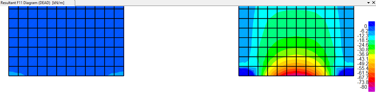
- Beam-Slab Interaction
Finally, we can see a comparison between two common modeling scenarios for composite structures:
- Left: A center-to-center Beam-Slab interaction.
- Right: A top-to-top Beam-Slab interaction, which more accurately represents the physical reality of a slab sitting on top of a beam.
As expected, the deflection is lower for the case with the top insertion point (right). It is also evident that membrane forces develop in the slab due to the axial interaction between the slab and the beam, an effect that is only captured when the correct insertion point is used.
Lastly, looking at the frame elements it is also notable that moments are lower for the case with the Insertion Point shifted from the center.
