
2D vs. 3D Modeling in 3DMacro: Clarifying the "Model Type" Selection
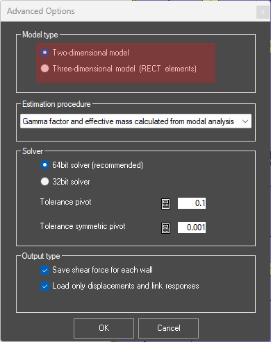
When configuring a project in 3DMacro, one of the critical settings located under the Advanced Options - Model type menu is the choice between “Two-dimensional model” and “Three-dimensional model (RECT elements)”.
While the intuitive choice for a full building analysis might seem to be the "Three-dimensional model," this setting fundamentally alters the computational formulation of the macro-elements. Understanding the mechanics behind these options is crucial for both solution accuracy and computational efficiency.
This article clarifies the technical differences between these modes and explains why the Two-dimensional model is the recommended standard for residential masonry structures.
1) The Technical Difference: Interface Springs
The core difference between the two model types lies in the mathematical formulation of the interfaces between macro-elements. 3DMacro utilizes a discrete element approach where non-linear behavior is lumped into interface springs.
- Two-dimensional model: When this option is selected, the software adopts a single set of springs at the interfaces between macro-elements. These springs are active only for the in-plane behavior of the wall. Consequently, each wall contributes stiffness and strength solely in its own plane. The out-of-plane stiffness of individual walls is effectively neglected in the global matrix.
- Three-dimensional model (RECT elements): In this mode, three sets of springs are generated at the interfaces. This configuration captures both in-plane and out-of-plane behavior. As a result, the mode shapes (modes of vibration) will reflect out-of-plane deformations of the walls. Bellow you can see the difference between 3D and 2D Model Type Option.
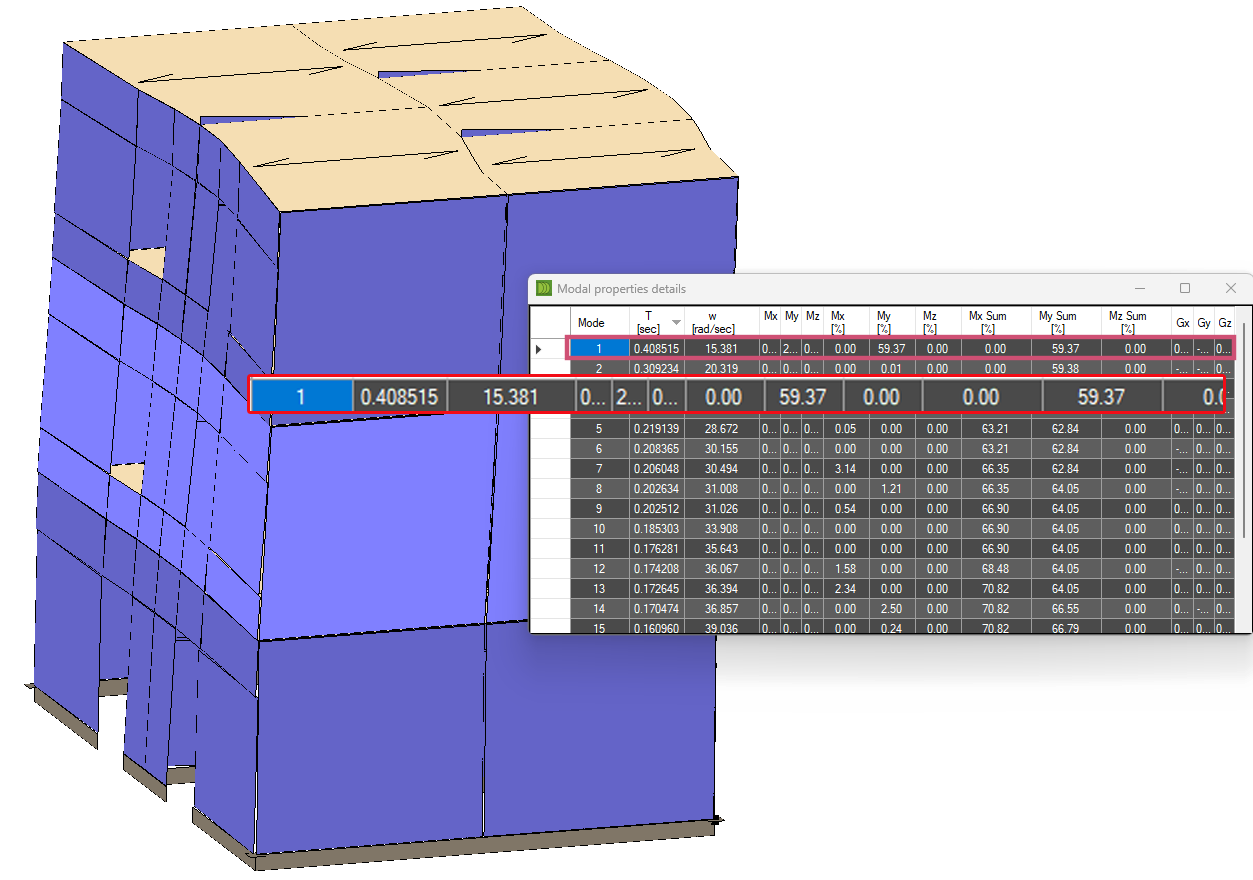
Model Type Option 3D
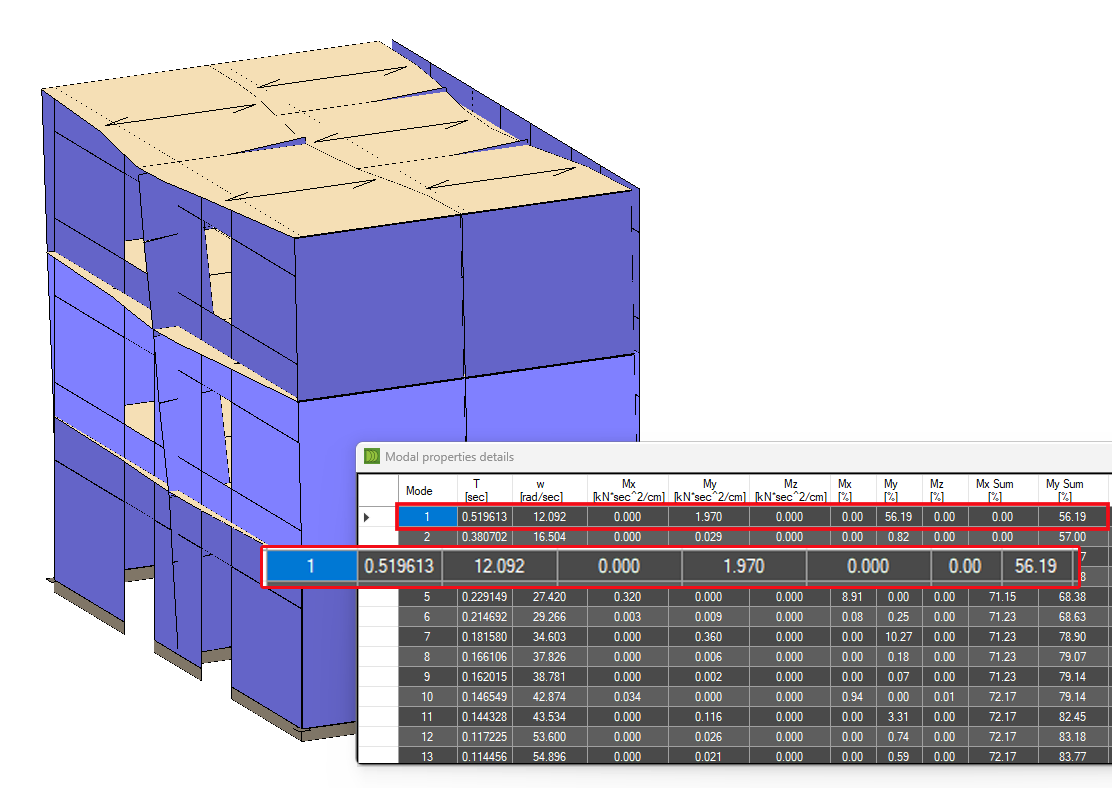
Model Type Option 2D
2) The Recommendation: Why Choose the "Two-dimensional Model"?
Despite the availability of the 3D element formulation, the developers strictly recommend using the "Two-dimensional model" for the majority of standard masonry building analyses.
This recommendation is based on the structural mechanics of typical masonry buildings and computational efficiency.
The "Box Behavior" Assumption
Most residential masonry structures are designed to exhibit "box behavior." The presence of stiffening elements—such as brick-concrete slabs, tie rods, and concrete ring beams (kerbs)—ensures that the walls work together as a coherent 3D unit.
- Global Accuracy: Because of this box action, the global seismic response is dominated by the in-plane shear and rocking of the walls. The 2D model accurately captures this global behavior.
- Out-of-Plane (OOP) Checks: The OOP mechanisms (local mechanisms) are generally checked a posteriori (after the global analysis) using kinematic limit analysis or specific local verification protocols, rather than being solved simultaneously in the global non-linear static (pushover) analysis.
Computational Efficiency
The "Two-dimensional model" offers a massive advantage in processing speed. By ignoring the out-of-plane degrees of freedom (DoFs) for the wall elements, the total DoFs in the computational model are reduced by approximately 60%. This allows for significantly faster iteration times and analysis of larger, more complex buildings without sacrificing accuracy regarding the global seismic capacity.
3) When to Use the "Three-dimensional Model (RECT elements)"
The full 3D model formulation is not obsolete; it is simply specialized. It is primarily devoted to isolated structures where box behavior cannot be assumed, and out-of-plane bending is a primary failure mode.
Typical Use Cases:
- Towers
- Churches and Bell Towers
- Free-standing walls
Critical Considerations for 3D Mode:
If you choose to use the Three-dimensional model, be aware of the following constraints:
- Mesh Refinement: To accurately capture the out-of-plane failure (specifically the correct position of horizontal plastic hinges along the height of a wall), you must use a very fine mesh refinement. A coarse mesh will likely yield unconservative or incorrect OOP failure mechanisms.
- Modelling Complexity: 3DMacro’s input architecture (Plan and Wall editors) is optimized for residential buildings composed of orthogonal walls. Modeling complex geometries typical of historical churches (e.g., cylindrical surfaces, apses, or vaults) can be difficult and may require significant workarounds compared to general-purpose FEM software.