
Modeling Loading Zones in ETABS and SAFE Using "None" Areas
Correct load distribution is a fundamental step in building any finite element model. This technical article demonstrates how to use an area property of the "None" type in ETABS to quickly and accurately define a specific loading zone without altering the structure's stiffness.

To illustrate this procedure and the associated precautions, we will use a practical case: the floor plan of a service building that includes a landscaped area. We will focus our attention specifically on this garden zone.
Modeling specific live loads, such as those originating from a garden area, requires the calculation model to accurately reflect the layout of these zones.
To understand the modeling strategy, the following image shows the ETABS calculation model overlaid with the architectural plan. This visualization helps to understand exactly where the load area should be positioned relative to the structural elements.
2. Applying the Load to the "None" Area
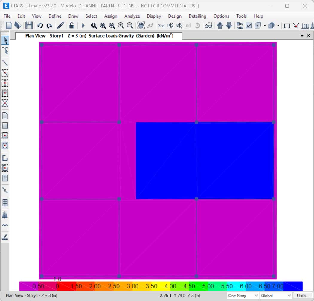
The next step consists of the actual modeling. We define an area with the "None" section property exactly over the previously delimited garden zone. Because it is a "None" object, this area has no self-weight and does not contribute to the slab's stiffness, serving exclusively as a load transfer surface.
In this example, we assigned a distributed load of 7 kN/m² to this area.
3. The Load Transfer Principle
It is fundamental to understand how ETABS interprets this object. The load applied to the "None" area is automatically transferred by the program to the nearest mesh nodes of the underlying structural elements (Slab).
4. Precautions: Mesh Compatibility and Accuracy
If the user does not intervene in the mesh discretization settings, the program does not automatically generate a mesh compatible with the boundaries of the "None" object. While it is advisable to ensure mesh compatibility for greater calculation rigor, it is not strictly mandatory in standard models, as the program's algorithm can distribute the load proportionally to the nearest nodes, even if they are physically distant.
However, if your project requires greater control and absolute rigor in accounting for and distributing these loads, the following advanced procedures are recommended:
-
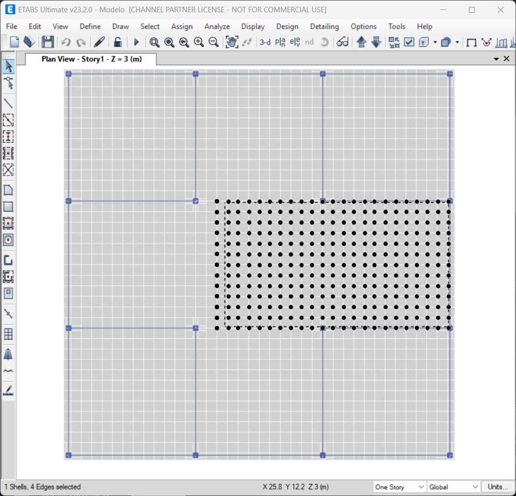
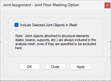
Include Joints in the Mesh Generator: Ensure that the corner nodes (vertices) of the "None" area coincide with or are added to the slab's mesh nodes. This forces the mesh to recognize the primary boundaries of the loading zone.
-
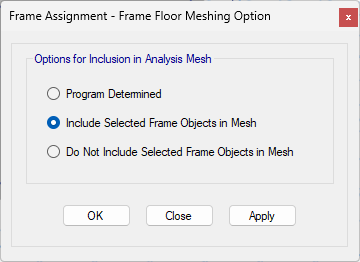
Include Frame Elements in the Mesh Generator: In very specific cases where the load path must be precise to the millimeter, frame elements—also with the "None" property—should be drawn along the entire perimeter of the loaded area. These boundary objects are then added to the slab's mesh generation constraints, ensuring perfect discretization along the boundary of the loaded zone.
In the images provided, one can see a zone where the mesh is not compatible with the "None" area object. As indicated, the tributary loads from the end nodes of the "None" object will be automatically transferred to the mesh nodes.

As a supplement to this article, you may consult the article Overlapping slab objects in ETABS and SAFE programs, which addresses the hierarchy of various slab elements.