
Parametric Definition of Links in CSiBridge
When starting bridge modeling in CSiBridge, one of the most confusing concepts is how the software connects the deck to the abutments and bents. This connection is provided by links of a specific length, which is determined by the various elements that make up the deck, such as the slab and girders.
The physical problem is straightforward: the center of gravity of the deck does not coincide with the top of the abutment. There is a physical space occupied by the slab, girders, and bearings. How does the software ensure the correct transfer of forces (especially bending moments generated by eccentricities) between these elements?
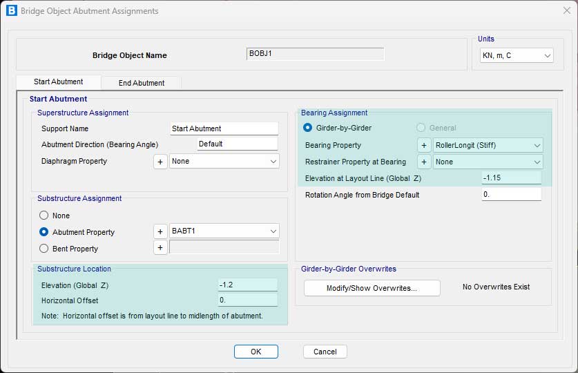
To ensure that the analytical model reflects reality, we need to configure two crucial sections: Substructure Location and Bearing Assignment. In the Substructure Location field, the elevation of the substructure is defined, which in this practical example represents the cap beam or abutment. In the Bearing Assignment field, the actual physical position of the bearing area and the type of boundary condition desired between the deck and the cap beam are established.
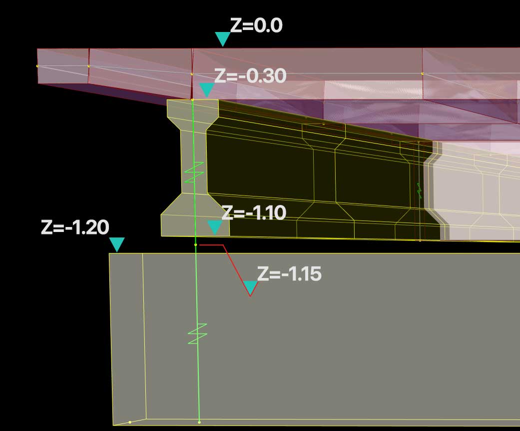
Defining the Gap Geometry (Substructure Location) The Layout Line is typically located at the top of the slab, at elevation Z = 0. From here, the program needs to know where the substructure begins.
Imagine a deck with a 0.30 m slab and 0.80 m I-girders. The bottom of the superstructure is at elevation -1.10 m. If we set the Elevation (Global Z) parameter of the Substructure Location to -1.20 m, we are creating a 0.10 m gap. This is the actual physical space where the bearing will be installed, between the deck girder and the abutment cap beam.
Positioning the Force Transfer (Bearing Assignment) Once the 0.10 m gap is created, CSiBridge inserts a link to connect the superstructure to the substructure. This is where the Bearing Assignment comes in: by setting the elevation to -1.15 m, we are positioning the spring halfway in the gap between the cap beam and the bottom of the I-girders (0.05 m below the I-girder and 0.05 m above the abutment).
If this elevation is incorrectly defined, the lever arm for the transfer of horizontal forces (such as seismic or braking loads) will be incorrect, generating artificial and erroneous bending moments in the substructure. Understanding these elevations is key to mastering the analytical model generated by CSiBridge.