
Mastering the VIS Design Wizard: A Practical Workflow for Fast and Reliable RC Pre‑Design
Turn automated reinforcement generation into a productive, controlled, and predictable part of your reinforced‑concrete design workflow.
The Design Wizard in VIS is built to deliver a coherent, continuous, and constructible reinforcement baseline for beams, columns, walls, and coupling beams at the very start of your project. Instead of hand‑drafting rebars from scratch, you begin with a stable, code‑aligned layout — then refine only where it adds engineering value.
This article explains every preference that affects beams, columns, and walls, plus the surrounding workflow (locking, safety multipliers, run, checks, and refinement), so you can get actionable results immediately.
1) What the Design Wizard Actually Does
- Produces real reinforcement layouts (not just required areas): number of rebars, diameters, spacing, and positions.
- Segments beams and columns intelligently to reflect practical cutoffs and rebar continuities.
- Preserves continuity across supports, joints, and stories wherever appropriate.
- Aims to satisfy strength, capacity design (when active), and detailing logic from the outset.
- For non‑straightforward locations, it intentionally leaves reinforcement unassigned and flags them for your judgment.
Outcome: a complete, engineering‑meaningful pre‑design that you can check and refine.

2) Beam Reinforcement Preferences — Everything You Control
Beams are governed by a small set of powerful concepts. Understanding them is the key to clean, consistent layouts.
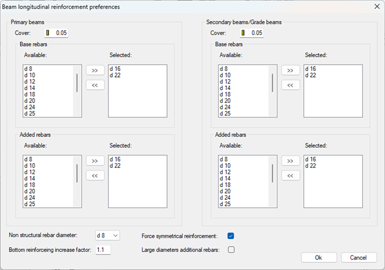
2.1 Base reinforcement (the backbone)
- The continuous top/bottom rebars that form the beam’s primary flexural system.
- Provides a stable baseline for calculations and constructibility across spans and supports.
2.2 Added reinforcement (targeted strengthening)
- Local rebars placed only where needed (moment peaks, shearcritical regions, localized demands).
- Not necessarily continuous — keeps the base layout clean while addressing hotspots.
Why the split matters:
Separating base from added reinforcement yields consistent, easily repeatable layouts (base) and precise, efficient local strengthening (added) without clutter.
2.3 Diameter lists (two lists = two roles)
- Provide one list for base rebars and another for added rebars.
- The Wizard selects from your lists to meet structural and detailing needs.
- Short, coherent lists produce more uniform, readable results project‑wide.
2.4 Symmetry option
- Enforce a symmetric layout across the beam (top/bottom or left/right, as applicable).
- Excellent for regular grids and modular designs where repetition and clarity save time.
2.5 Primary vs secondary beams
- Primary beams: part of the main lateral system; receive seismic‑related detailing when that design mode is active.
- Secondary beams: treated without the same seismic capacity requirements.
3) Column Reinforcement Preferences — Continuity, Splices, Free Reduction, Optimization
Columns demand vertical robustness, simplicity of detailing, and consistent behavior from story to story. The Wizard gives you explicit control.
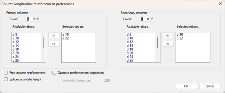
3.1 Preferred diameters for primary and secondary columns
 Separate allowable diameter lists for primary vs. secondary columns.
- Enables stricter control for the seismic system while allowing different ranges where ductility is less critical.
3.2 Free column reinforcement (allowing downward reduction)
This toggle governs whether longitudinal reinforcement may decrease as you go downward through stories.
- OFF (the conservative default): Reinforcement does not decrease in lower stories. If the upper story ends up with 8 bars, the lower ones will use at least 8 bars as well.
Benefit: vertical continuity, robustness, and simpler detailing through the column stack. - ON: Allows the Wizard to reduce reinforcement in lower stories when the required area is smaller.
Benefit: potential steel savings.
Tradeoffs: less uniformity, more drawing complexity, and more attention to laps and transitions.
Use this decision to match your project priorities: uniform constructibility vs. minimum weight.
3.3 Splice positioning (base or mid‑height)
Choose where to place the main longitudinal splices:
- At the base — often convenient near the foundation or where confinement is high.
- At mid‑height — can relieve congestion near joints and help with lap staggering.
This setting helps you balance constructibility, congestion management, and joint performance.
3.4 Automatic optimization for rectangular columns — how the algorithm really works
For rectangular columns, VIS uses a structured, incremental algorithm to determine bar distribution. The behavior depends on whether Optimization is ON or OFF.
When Optimization is OFF (standard behavior)
- Start with the minimum bars required by code:
- One rebar at each corner.
- The minimum number of intermediate bars on each edge (max spacing 30 cm).
- Design using this exact bar layout — compute required steel area and convert to equivalent diameter.
- If the required diameter fits your allowed list, the process stops.
- If not, the layout must be expanded.
- Iterate by adding one rebar to each edge until a valid solution is found or the maximum reinforcement is reached.
In short: without optimization, reinforcement expands uniformly on all faces until a satisfactory layout is achieved.
When Optimization is ON (enhanced search for better layouts)
With Optimization enabled, the Wizard doesn’t just expand all sides equally.
It explores three independent reinforcement patterns in parallel and later chooses the best one:
- Path A — Uniform expansion on all edges: add one bar to every edge, recheck, repeat as needed (same as standard mode).
- Path B — Expand along the first pair of opposite edges: keep the other two edges at minimum until needed.
- Path C — Expand along the second pair of opposite edges: identical logic applied to the other pair of faces.
Final selection (Optimization ON): After all three paths converge to valid solutions, the Wizard compares total reinforcing steel (within your tolerance) and selects the layout that uses the least steel, while favoring the most homogeneous distribution.
Meaning: Optimization ON searches multiple reinforcement patterns and chooses the most efficient and constructible option — not just the first one that works.
4) Wall (Core) Reinforcement Preferences — Boundary Regions, Spacing Logic, Spandrels
Walls and cores require a different kind of control — especially at boundary regions.
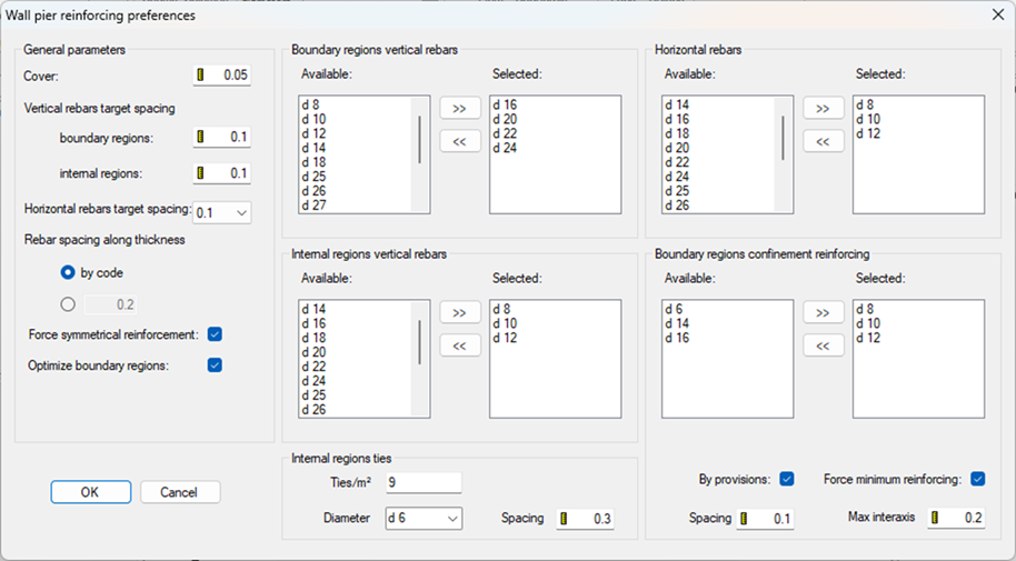
4.1 Boundary regions vs. internal regions
For each wall/pier you define:
- Allowed longitudinal diameters.
- Target vertical spacing for boundary regions and internal regions.
- Maximum spacing through wall thickness.
- Optional optimization of boundary‑region length.
This allows you to express typical core‑wall behavior: strong, dense boundary zones and a more moderate internal web.
4.2 How the Wizard chooses bar diameters for walls
- The Wizard starts from the smallest diameter.
- Computes minimum spacing required.
- If spacing meets your target, that diameter is used; otherwise, next diameter.
- Spacing targets control diameter selection.
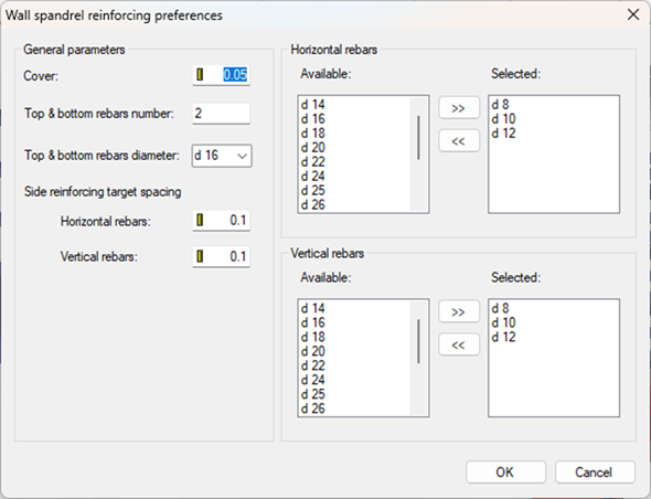
4.3 Spandrels (coupling beams)
For spandrels, you can specify:
- Edge reinforcement (top and bottom) to ensure the coupling action is properly anchored.
- Internal longitudinal rebar via diameter lists and spacing targets, following the same “smallest diameter that meets target” logic.
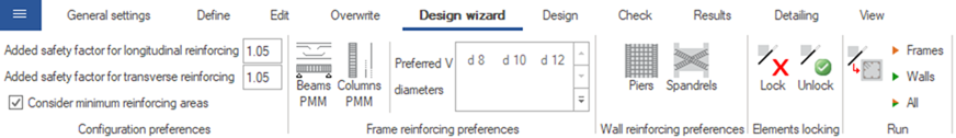
5) Safety Multipliers — Built‑In Robustness for Pre‑Design
Before translating demand into actual bars, you can apply small multipliers to:
- Longitudinal reinforcement
- Transverse reinforcement
These multipliers gently increase the reinforcing demand used by the Wizard, adding a buffer against modeling approximations and rounding effects.
If you have no special reason to change them, the default values are sensible for earlystage predesign.
6) Locking Elements — Keep What You've Already Refined
Any beam, column, or wall can be locked before running the Wizard:
- Locked = reinforcement remains unchanged.
- Unlocked = may be redesigned.
Locking is essential when:
- Locking is essential when:
- You have manually tuned critical regions,
- Lower stories or transfer elements must remain as is,
- Wall legs around openings require custom confinement.
It is the safest way to iterate without losing intentional engineering decisions.
7) Running the Wizard — What Happens Next
When you click Run:
- The Wizard segments frame elements where needed.
- It assigns longitudinal and transverse reinforcement from your preferences.
- It maintains continuity across supports and stories.
- It applies strength/capacity/detailing logic.
- It flags ambiguous or nonstraightforward locations for manual engineering.
Immediately afterward, execute projectwide checks:
- Strength (PMM and shear),
- Capacity (if seismic design is active),
- Serviceability,
- Detailing provisions.
This populates the result dashboards and pinpoints where to apply refinement.
8) Refinement — Use the Editors, Not a Blank Canvas
Refine within the dedicated editors:
- Frame Reinforcement Editor — beams and columns
- Wall Reinforcement Editor — piers and spandrels
These tools let you:
- Adjust bar lengths, diameters, and positions,
- Modify or create reinforcement stretches,
- Edit stirrups/ties and transverse wall reinforcement,
- Copy reinforcement across similar members or stories,
- Rerun checks directly in the editing environment.
This is real engineering work — focused, iterative, and supported by immediate feedback.
9) A Simple, Repeatable 9‑Step Workflow
- Import the analysis model and set units/code.
- Load saved settings (optional): apply your previously saved Wizard Settings and Code Settings so you start with your team’s standards instead of reconfiguring each project.
- Fill beam/column/wall preferences (diameters, spacing targets, splices, optimization, primary/secondary).
- Lock any elements you don’t want changed.
- Run the Design Wizard.
- Run strength/capacity/serviceability/detailing checks.
- Refine only where checks indicate (Frame/Wall Reinforcement Editors).
- Export layouts, drawings, or IFC.
- Update cycle (when the analysis model changes):
- Reimport the new model version.
- Import reinforcement from the previous VIS file for all elements whose geometry still matches.
- Run the Wizard only for a selection: execute it just on the members where reinforcement could not be imported (e.g., changed geometry), keeping the rest intact.
- Recheck and adjust locally as needed. For a stepbystep example of this flexible loop between SAP2000 and VIS, see the Structural Academy article: Flexible workflow between SAP2000 and VIS.
10) FAQ — Clearing Up Common Doubts
Q1: Why do I see too many different bar diameters in beams?
Your diameter lists might be too long. Keep them short and consistent for more uniform layouts.
Q2: My column reinforcement changed between stories — is that expected?
If Free column reinforcement is ON, the Wizard may reduce bar count in lower stories. Turn it OFF for monotonic nondecreasing layouts.
Q3: The wall ends look very dense — normal?
Check your boundaryregion spacing targets and the diameter list. Tight spacing targets drive denser layouts; adjust targets or allow a different diameter set.
Q4: Why are some regions left without bars?
They’re intentionally left unassigned because the solution is not straightforward there. Open the editor, design them explicitly, and recheck.