
Response Spectrum Analysis in Hybrid Structures with Different Damping Ratios
Seismic analysis of hybrid structures — composed of different materials such as reinforced concrete and steel — presents specific challenges when considering different damping ratios by material. Traditionally, response spectra used in structural analysis software assume a single critical damping value, usually 5%, as a reference.
However, hybrid structures require a more refined approach, as different materials dissipate energy differently. For example, Eurocode 8 defines the response spectrum for 5% critical damping and proposes a correction factor to adjust the spectrum ordinates for other damping values.
In this article, we will demonstrate step by step how to apply this correction mode by mode using ETABS software, which calculates modal damping and automatically applies the Newmark and Hall correction factor.
Example Objective
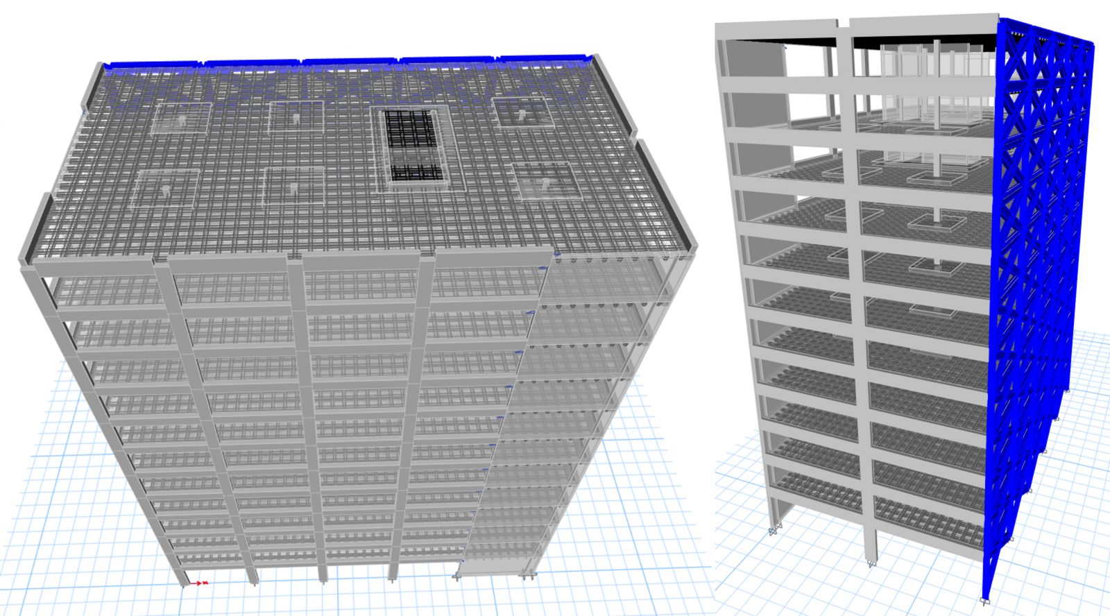
Model a 12-story structure, predominantly reinforced concrete, with a steel façade, and perform a response spectrum analysis considering:
- 5% critical damping for reinforced concrete
- 2% critical damping for steel
Step by Step
Below we describe the steps performed in the ETABS model to apply different damping values by material and observe the effects on the spectral analysis. To allow readers to reproduce these steps and validate the results, we provide the ETABS model used in this example.
The model damping_RSA_0.EDB includes the 12-story hybrid structure with a steel façade, already configured with initial material properties. Users can follow the steps and directly observe vibration modes, modal damping values, and effects on spectral acceleration. The model damping_RSA_1.EDB corresponds to the final state after implementing the proposed procedures.
- Identify the Hybrid Structure
- 12-story building model.
- Main structure in reinforced concrete.
- Steel façade on one side.
- Define the Response Spectrum Function
- Use a spectrum defined for 5% critical damping.
- Confirm that this value is only indicative and does not change the spectrum ordinates.
- Check Initial Damping
- By default, the model assumes 5% damping for all modes.
- Material damping is initially set to zero.
- Analyze Vibration Modes
- Modes 1 and 2: dominated by concrete structure
- Mode 3: significant deformation in the steel façade
- Activate Material Damping
- Change material properties:
- Concrete: set 5% damping.
- Steel: set 2% damping.
- Adjust the damping value in the response spectrum load case to zero to avoid unintended sums.
- Change material properties:
- Re-run the Analysis
- Check new damping values mode by mode.
- Confirm that mode 3 now shows damping below 5%.
- Interpret Results
- Compare acceleration values before and after activating material damping.
- Observe that modes with damping below 5% show amplified accelerations.
Video Demonstration
Watch the video below to see how to apply different damping values by material in ETABS and how this affects modal and spectral analysis results.
The video complements the steps above, visually illustrating the logic of assigning damping, activating material damping, and comparing results.
Comparison Chart of Correction Factors
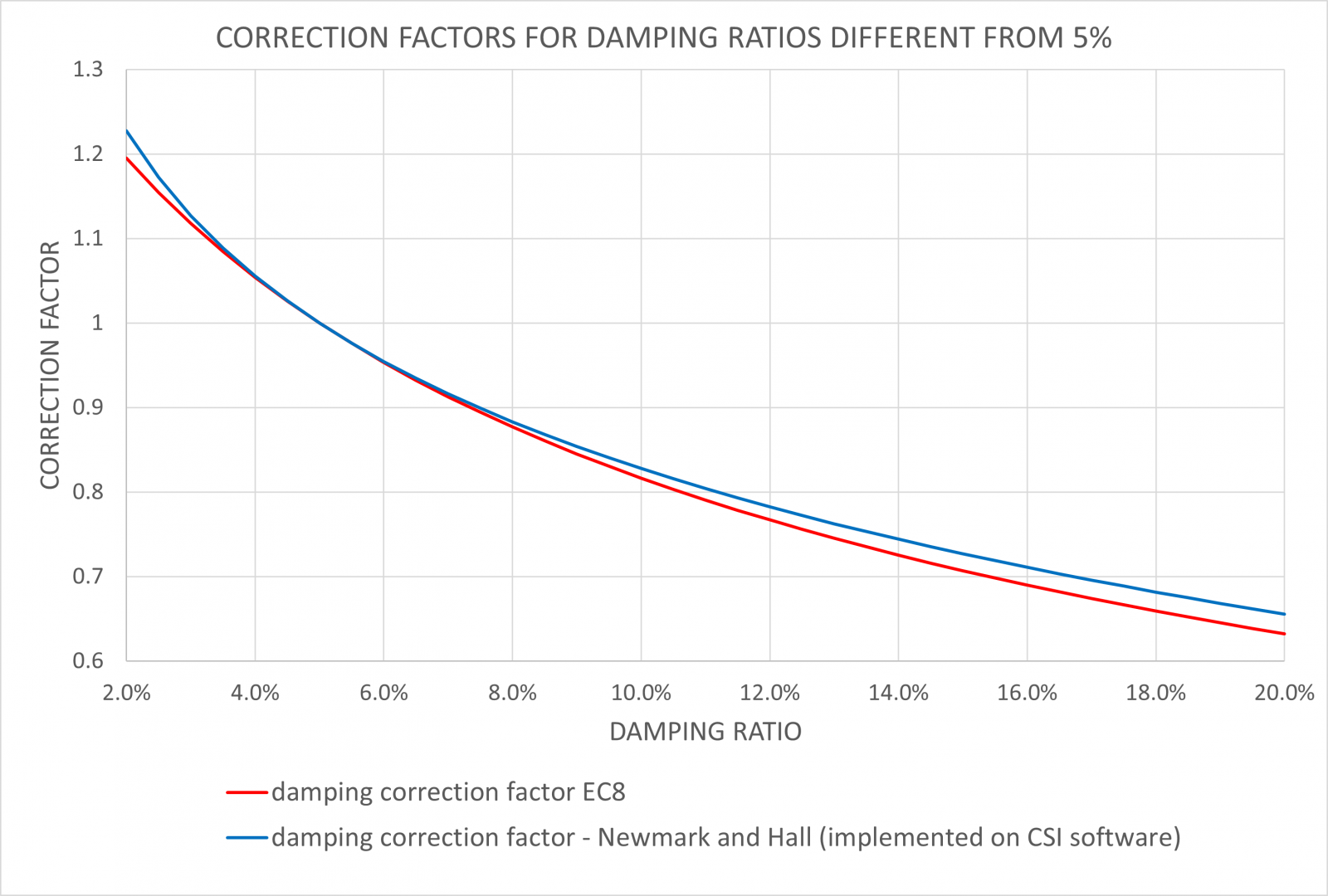
This chart shows that for damping values between 2% and 20%, both correction factors are very similar. However, the Newmark and Hall factor, automatically used in CSI software (ETABS, SAP2000, CSiBridge), is slightly higher than Eurocode 8 for any damping level.
This difference makes the Newmark and Hall method conservative, as it systematically results in slightly higher acceleration values after spectral correction. In other words, regardless of whether modal damping is lower or higher than the reference value (usually 5%), the Newmark and Hall method leads to a slightly more conservative seismic response — which is desirable in structural design contexts.
Numerical Demonstration
During analysis, the response spectrum curve will automatically adjust from the function damping value to the actual damping present in the model. The velocity-based correction formula (Newmark and Hall, 1982) used in the calculation is as follows (log = natural logarithm):

Thus, we can easily demonstrate how the acceleration for mode 3 was obtained:
A2 = 0.164628 x 9806.7 x (2.31 – 0.41 x ln 3.56) / (2.31 – 0.41 x ln 5)
A2 = 1750.7 mm/s2
Conclusion
This article provides a practical approach to applying spectral corrections mode by mode in hybrid structures, using modal damping calculated automatically by ETABS. By activating material damping and using the Newmark and Hall correction factor, it is possible to adjust the response spectrum ordinates consistently with the dynamic reality of the structure.
The decision to consider different damping values by material rests with the responsible engineer, based on the nature of the structure, project objectives, and regulatory requirements. This article does not intend to recommend this practice as mandatory but rather to provide the technical means to implement it rigorously and efficiently in CSI software.