
Effective Length vs Unbraced Length: Key Differences and their application in CSI Software
Structural stability is a critical requirement in the design and analysis of frames, particularly under compression or bending loads. Two fundamental parameters defining structural stability, "effective length" and "unbraced length," are often confused or used interchangeably. However, they serve distinct purposes. This article explores these concepts, their differences, and their practical use in CSI Software for structural steel design.
What is Unbraced Length?
Unbraced length refers to the actual physical length of a frame between two points of lateral support. This is the unsupported span where lateral or torsional buckling can occur.
For example:
- In beams, the unbraced length is the distance between lateral supports or braces that prevent lateral movement.
- In Columns, typically, the unbraced length is the distance between 2 stories.
Key Considerations:
- Geometric Nature: Unbraced length is a straightforward measure based on the physical layout of the structure.
- Critical Role in Design: It directly affects a member's susceptibility to lateral-torsional buckling (in beams) and lateral buckling (in columns).
Design and Unbraced Length
In CSI Software, this parameter is defined during modeling and is influenced by the geometry and the placement of lateral bracing. Users should carefully confirm and adjust the unbraced lengths assumed by the program to reflect the real conditions.
What is Effective Length?
Effective length accounts for the overall buckling behavior of members, incorporating boundary conditions and the structural system’s stiffness. It is calculated as the actual length of the member (L) multiplied by an effective length factor (K).
For example:
- A pinned column may have a factor K = 1.0.
- A column in a sway frame, subject to lateral instability, may have K > 1.0, reflecting higher buckling risks.
Determinants of K-Factor:
- Joint stiffness.
- Sway or non-sway characteristics of the frame.
- Support conditions (pinned, fixed, etc.).
Unlike unbraced length, effective length is a combined stability parameter rather than a geometric property.
Applying Unbraced and Effective Lengths in CSI Software
While CSI Software offers extensive tools for modeling and analysis, assigning unbraced and effective lengths requires thoughtful input and judgment. These lengths are critical for code-compliant designs, especially in EC3.
Defining Effective Length (K-Factors) in CSI Software
The effective length factor (K) adjusts based on whether the frame is sway or non-sway:
- K1 (Non-Sway Frame): Typically ≤ 1.0.
- K2 (Sway Frame): Typically ≥ 1.0.
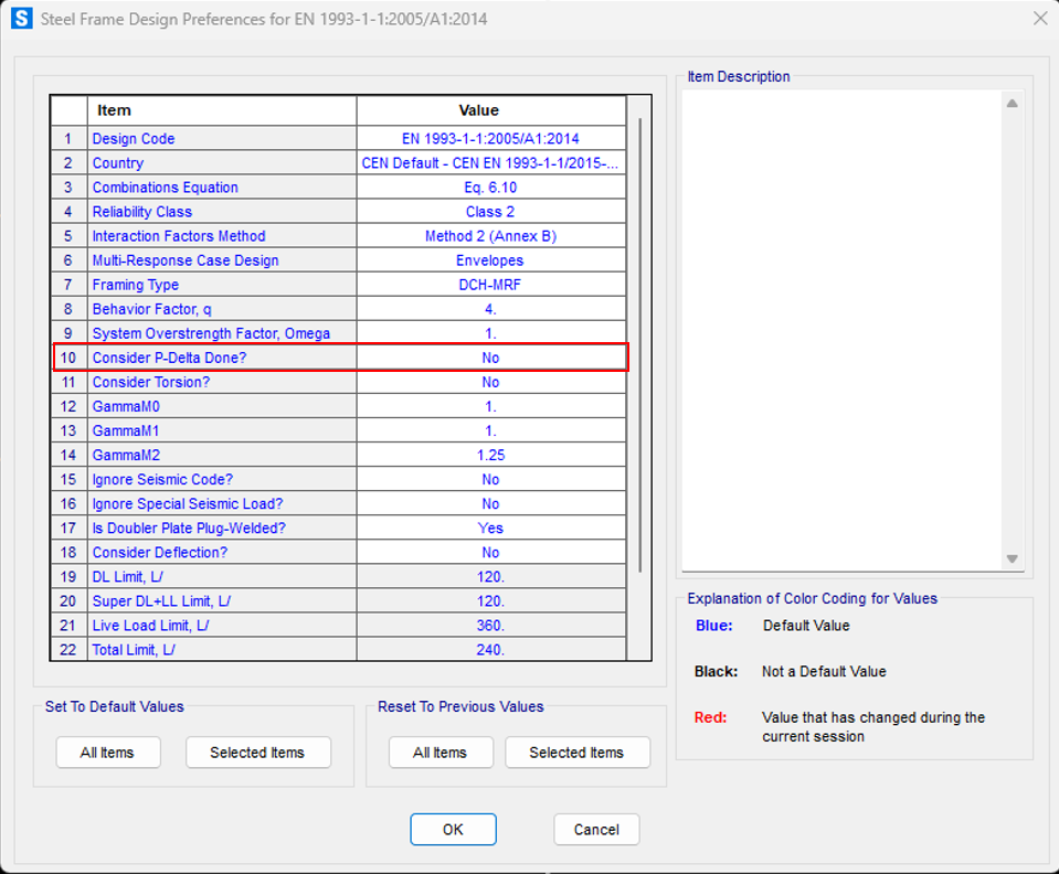
Important Notes for Eurocode 3:
- Unless overwritten, K factors for beams are always 1;
- K2 influences the calculation of Nb,rd;
- K1 affects Kij factors.
- In Steel Design Preferences, selecting “P-Delta Done = Yes” indicates that a P-Delta load case or a buckling analysis was performed prior to design, and K2 will automatically default to 1.0
Global P-Delta effects – Eurocode 3, clause 6.3
If global P-Delta effects are not relevant (αcr ≥ 10), columns can be checked using the following options:
- K2 = 1.0, assuming buckling lengths equal to actual lengths. This can be easily achieved through the option “P-Delta Done = Yes”.
- Linear analysis disregarding global second-order effects.
If global P-Delta effects are relevant (αcr < 10), columns can be checked using the following options:
- K2 = 1.0, assuming buckling lengths equal to actual lengths. This can be easily achieved through the option “P-Delta Done = Yes”.
- Both global imperfections and second-order effects must be considered in the analysis. Design load combinations should be converted to nonlinear P-Delta load cases.
Depending on the National Annexes, in some countries the following procedure is allowed when global P-Delta effects are relevant (αcr < 10):
- K2 automatically computed for sway frames, or input manually according to sway instability mode.
- Linear analysis disregarding global second-order effects.
To learn more about global P-Delta effects in SAP2000, watch this video reference.
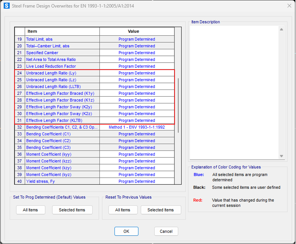
Steps to Define or Modify Length Parameters
- Automatic Calculation: Use software built-in functionality to compute K-factors (K1 and K2) based on frame geometry and stiffness properties.
- Manual Adjustment: Where boundary conditions require customization, overwrite effective length (K1 and K2) and unbraced length (L) manually for specific frame elements.
Examples
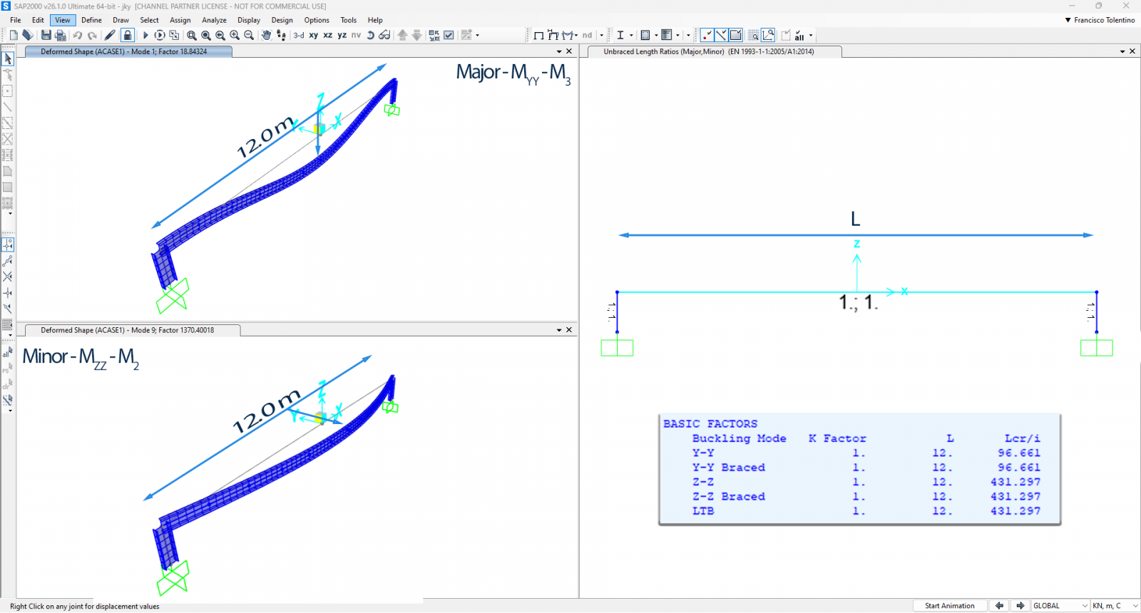
The following beam is modeled as a single frame object with a 12.0 meter span. Effective Length (K factors) are 1 and Unbraced Length (L) is 12 meter.
| Lcr (y) = 1 x 1 x 12 = 12 meters | ✅ |
| Lcr(z) = 1 x 1 x 12 = 12 meters | ✅ |
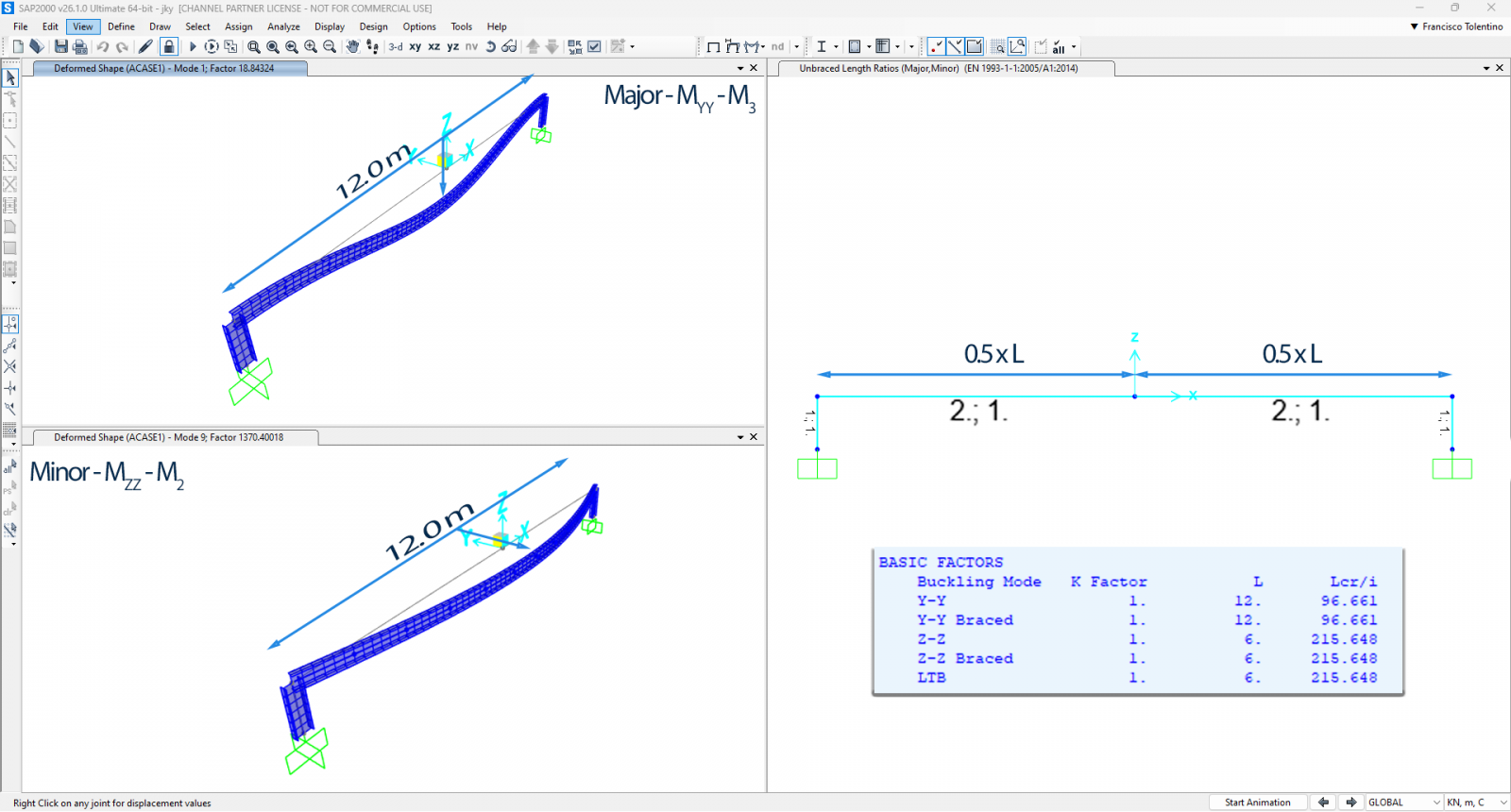
Now the same beam is modeled with two frame objects, 6.0 meters span each. In this case, the middle joint is considered as a lateral bracing point for weak axis buckling (Mzz). The unbraced length ratio (Lz) must be manually adjusted/overwritten to account for this condition.
| Lcr (y) = 1 x 1 x 12 = 12 meters | ✅ |
| Lcr(z) = 1 x 1 x 6 = 6 meters | ❌ |
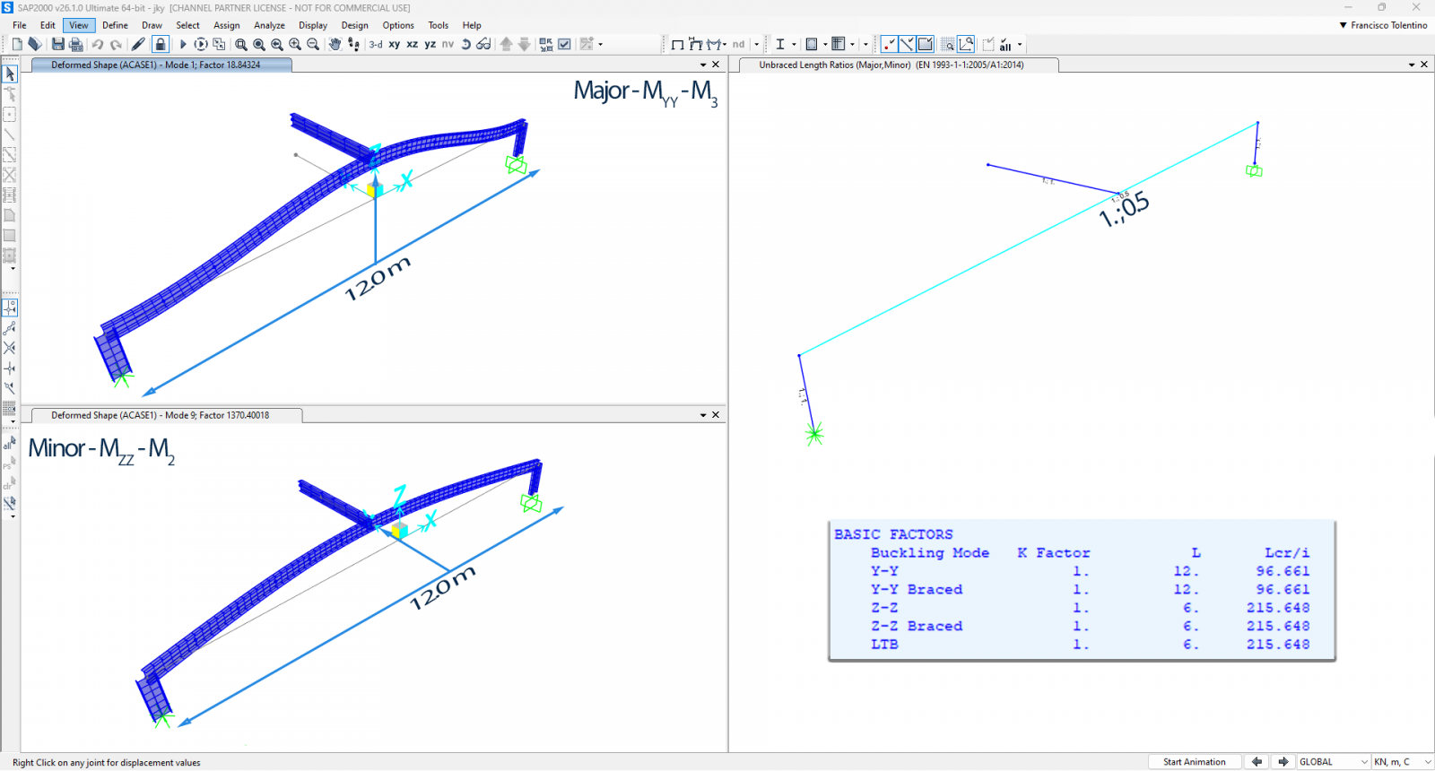
Another case could be the following beam, modeled as a single frame object with a 12.0 meter span and a cantilever beam connected at its midpoint. In this case, the cantilever is considered a lateral bracing point for weak axis buckling (Mzz). The unbraced length ratio (Lz) must be manually adjusted/overwritten to reflect this condition.
| Lcr (y) = 1 x 1 x 12 = 12 meters | ✅ |
| Lcr(z) = 1 x 1 x 6 = 6 meters | ❌ |
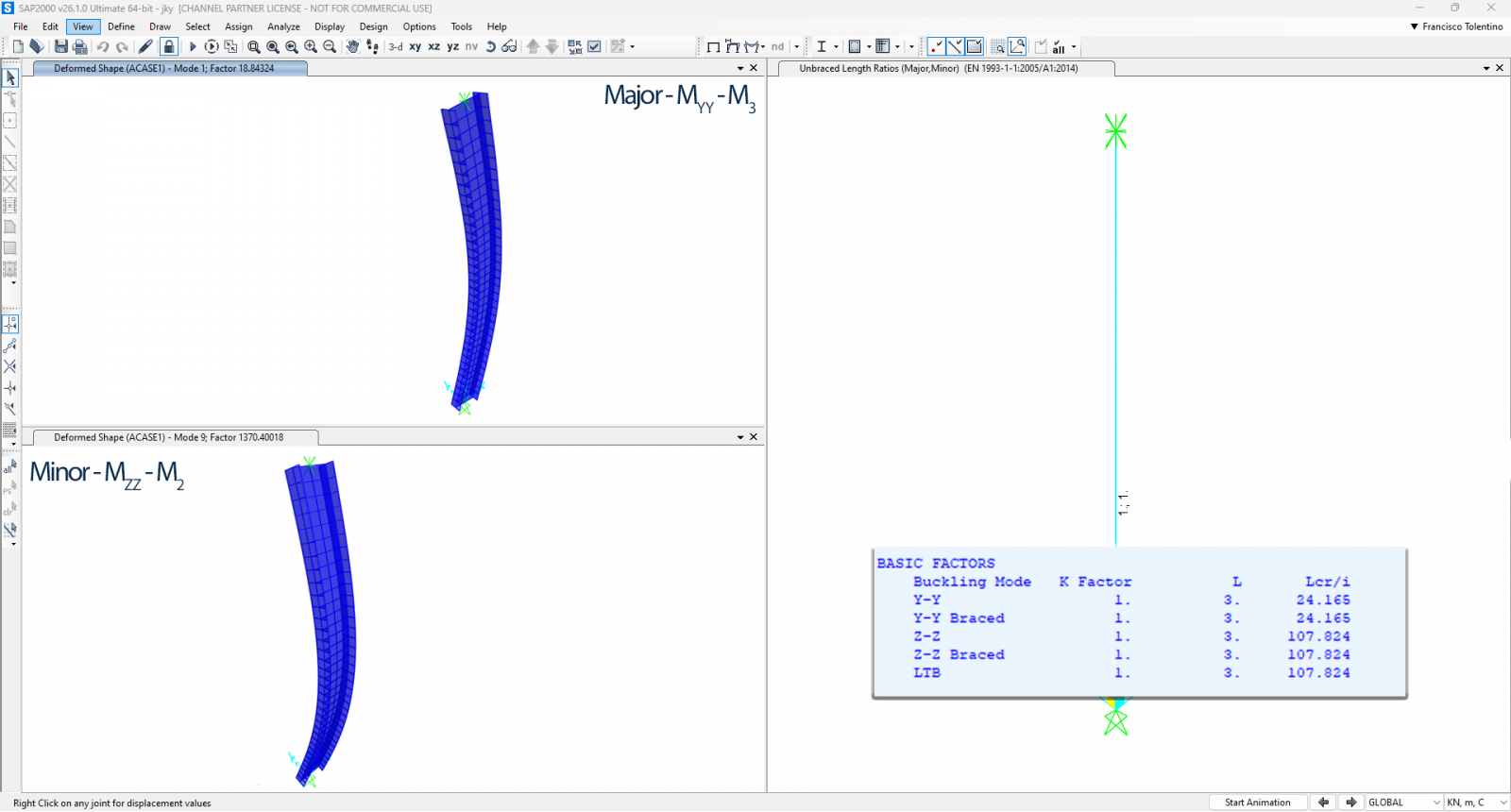
Simply supported column with 3.0 meters span.
| Lcr (y) = 1 x 1 x 3 = 3 meters | ✅ |
| Lcr (z) = 1 x 1 x 3 = 3 meters | ✅ |
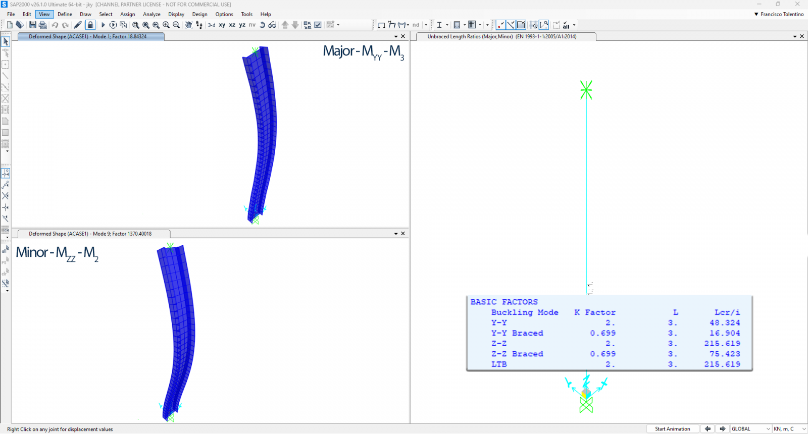
Pinned-Fixed column with 3.0 meters span. Note that for this case, there are 2 cases, one for sway mode and another for non-sway mode. Both are considered for design.
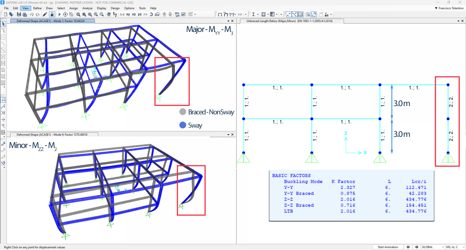
A multistory building with a 6-meter-high column is modeled using two frame segments, each 3.0 meters in length.
Conclusion
Understanding the interaction of unbraced length and effective length is essential for accurately design structures. While unbraced length is purely geometric, effective length reflects additional stability factors like boundary conditions and sway behavior.
In CSI Software, careful attention must be given to defining these parameters, ensuring they align with the code requirements (e.g., EC3) and actual structural constraints. Leveraging software advanced analysis capabilities, structural engineers can optimize designs while ensuring safety. However, it is critical to cross-verify software outputs with hand calculations and design codes, especially for critical structural elements.
For more information, refer to the official SAP2000 manuals and design code references.