
The Layered Shell Element in CSI Software: A Technical Overview
This article provides an overview of the Layered Shell finite element available in Computers & Structures, Inc. (CSI) software products such as SAP2000, ETABS, and CSiBridge. The Shell element is a type of area object used for modeling membrane, plate, and shell behavior in planar and three-dimensional structures. While the Shell element has two distinct formulations, homogeneous and layered, this article focuses specifically on the Layered Shell, which offers advanced capabilities for modeling complex material behavior, including nonlinearity.
CSI software provides a powerful tool for structural design, but users must understand the basic assumptions of the software modeling, analysis, and design algorithms and compensate for aspects not addressed. It is imperative to read the analysis reference manual and understand the assumptions and procedures before using the analysis features. Note that not all features described may be available in every level of each program.
Overview of the Shell Element
The Shell element is a three- or four-node formulation that combines membrane and plate-bending behavior. It is based on isoperimetric formulation.
The homogeneous shell formulation combines independent membrane and plate behavior, offering choices between thin-plate (Kirchhoff) and thick-plate (Mindlin/Reissner) formulations. The layered shell formulation utilizes the thick-plate (Mindlin/Reissner) formulation, which includes the effects of transverse shear deformation, for bending behavior.
Layered Shell Section Parameters
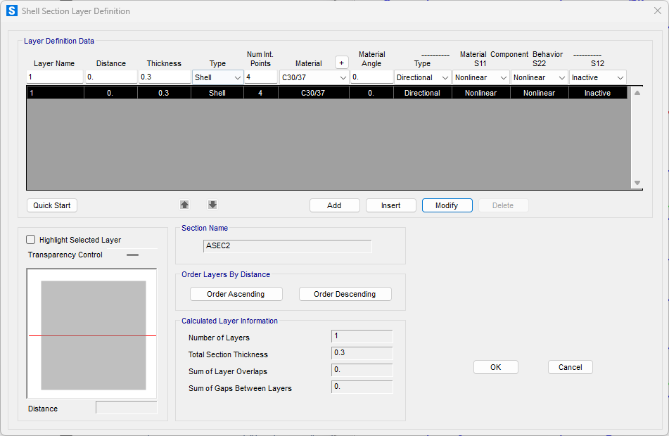
When defining a layered shell section, several key parameters allow for precise control over its behavior:
- Distance: Specifies the distance from the shell element's reference surface—which is derived from the shell object's joint location combined with any offsets—to the mid-height of the particular layer. A positive distance is measured along the positive local 3-axis of the shell object.
- Thickness: Defines the individual thickness of each layer. The overall section thickness is then calculated by the program based on the sum of all specified layer thicknesses, automatically accounting for any overlaps or gaps between layers. It is important to note that area section thickness and joint offset overwrite assignments, which might apply to homogeneous shells, do not affect layered shells.
- Type: This drop-down list allows the selection of the behavioral model for each layer: ◦
- Membrane: Models only in-plane (translational) behavior, utilizing a strain-projection method for membrane deformation within the layer.
- Plate: Models only out-of-plane bending behavior, including two-way rotational stiffness components and a translational stiffness component normal to the element plane. The thick-plate (Mindlin/Reissner) formulation, which inherently considers transverse shear deformation, is always applied for bending in layered shells.
- Shell: Models the full coupled membrane and plate behavior. This option provides comprehensive shell behavior unless all defined layers are exclusively set to either membrane or plate behavior. Full-shell behavior supports all forces and moments, with the exception of the "drilling" moment, which is not used for layered shells and should not be loaded.
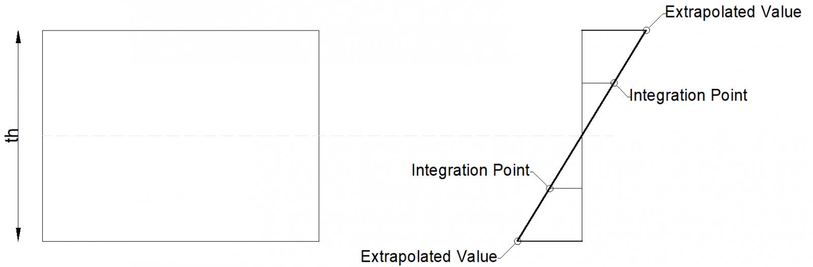
- Num Int. Points (Number of Integration Points): This value specifies the number of numerical integration points through the thickness of the layer. The program automatically determines the locations of these points using standard Gauss-quadrature rules to ensure accuracy in the analysis.
- Material: Allows the selection of a pre-defined material type for each layer. The layered shell can incorporate temperature-dependent, orthotropic material properties. The material properties used by the shell section include the moduli of elasticity (e1, e2), shear moduli (g12, g13, g23), and Poisson’s ratio (u12).
- Material Angle: If applicable, this parameter defines the material orientation within the layer. The angle is measured counterclockwise from the local 1-axis of the shell object to the local 1-axis of the material itself.
- Material Component Behavior: This option, available as a "Type" drop-down list, determines how the stress-strain relationships are handled for the membrane components (σ11, σ22, σ12):
- Directional: Applicable to all material types. In this mode, the behavior of nonlinear components is derived from the material’s uniaxial nonlinear data, and each component (σ11, σ22, σ12) acts independently. If any of the three components are set as nonlinear or inactive, the linear components will follow an uncoupled isotropic linear stress-strain law, nonlinear components will use their specified nonlinear stress-strain relationship, and inactive components will assume zero stress, effectively uncoupling the components as if Poisson's ratio were zero.
- Post-yield or Cracked Material Behavior: After yield or cracking, the material modulus changes and the Poisson’s ratio is neglected.
- Coupled: This option is available for concrete and steel materials when coupled nonlinear data has been defined for the material property. When selected, all three membrane stress components (σ11, σ22, and σ12) are treated as nonlinear, and their behavior is determined by the material's coupled nonlinear data.
- For concrete material, "Coupled” behavior specifically leverages the Modified Darwin-Pecknold 2-D Reinforced Concrete Material Model. This advanced model is a two-dimensional concrete material model designed to directly account for the intricate interaction between bending and shear within shear wall structures. In real-world applications, particularly in "squat" walls, there is significant coupling between axial-bending and shear forces, where the shear strength can be substantially influenced by axial-bending effects. By using this coupled formulation, the software can provide a more realistic representation of concrete behavior under complex loading conditions.
- For steel materials, "Coupled" Type uses the Von Mises approach to compute the stresses.
Note: For the layered shell section, time-dependent behavior is not currently supported.
Modeling Considerations
Joint Connectivity and Shape Guidelines: For three- or four-node Shell elements, ensure the inside angle at each corner is less than 180°, ideally near 90° or in the range of 45° to 135°. The aspect ratio (ratio of longest to shortest dimension, or longer to shorter distance between midpoints of opposite sides for quadrilateral) should ideally be near unity and should not exceed 10. For quadrilateral elements, joints don't have to be coplanar, but the angle between normals at corners (measure of twist) should be less than 30°, and should not exceed 45°. The thick-plate and layered formulations are more sensitive to large aspect ratios and mesh distortion than the thin-plate formulation.
Forces and Output
Internal force and stress output for Shell elements are evaluated at the standard 2-by-2 Gauss integration points and extrapolated to the outer joints. Principal values and their associated principal directions in the element local 1-2 plane are available for single-valued Load Cases and Load Combinations.

Convergence and Nonlinear Analysis
Nonlinear analysis is required to account for nonlinear material behavior in layered shells. This can be considered in nonlinear static analysis and in nonlinear direct-integration time history analysis.
Numerical considerations for nonlinear analysis with layered shells, especially those using complex material models, may require smaller time steps to converge compared to models with directional material models. Iteration for equilibrium is recommended for models having significant geometric nonlinearity.
Modified Darwin-Pecknold 2-D Reinforced Concrete Material Model
Basis and Capabilities: The model is based on the Darwin-Pecknold model, incorporating consideration of Vecchio-Collins behavior. It represents concrete compression, cracking, and shear behavior under both monotonic and cyclic loading, considering the stress-strain components σ11-ε11, σ22-ε22, and σ33-ε3343. A state of plane stress is assumed. A key assumption is that a uniaxial stress-strain relationship can be applied along each of the principal material axes.
Numerical Considerations: Compared to directional material models, the Modified Darwin-Pecknold model exhibits a higher degree of nonlinearity. Shell elements using this material employ a 2-by-2 numerical integration formulation in the plane. Due to the higher nonlinearity, this model may require smaller time steps to converge in analysis. Mesh refinement is also suggested when using shell elements with this material.
Conclusion
The Layered Shell element in CSI software is a versatile tool for modeling structural components with complex material behavior through their thickness, particularly useful for nonlinear analysis of elements like concrete walls and slabs. By allowing definition of individual layers with varied properties and behaviors, it enables detailed representation of composite action and material nonlinearity. Engineers utilizing this element, especially with advanced material models like the Modified Darwin-Pecknold, should carefully consider the modeling guidelines, meshing requirements, and numerical considerations to ensure accurate and reliable results. Consulting the specific sections in the CSI Analysis Reference Manual and relevant technical notes for detailed information is essential for effective use of this powerful finite element.