
Mesh Compatibility and Simplifications When Using Edge Constraints in CSI Programs
The introduction of Edge Constraints in structural analysis software such as SAP2000 has revolutionized the compatibility of non-coincident meshes. This functionality greatly reduces engineers’ manual efforts and speeds up the modeling of complex systems. However, using it requires a solid understanding of its behavior and limitations to ensure reliable analyses.
This article is intended for structural engineers and explores the following topics related to Edge Constraints: concept, advantages, possible simplifications, and precautions when using them in CSI software, such as SAP2000 and ETABS.
What Are Edge Constraints?
Edge Constraint is a feature implemented in CSI software that automatically reconciles displacements and rotations of joints in non-compatible meshes. This mechanism is particularly useful in situations where manually creating coincident meshes would be impractical or overly complex, such as transitions between refined meshes and coarser ones.
Initial Problem: Non-Coincident Joints
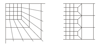
When two finite element meshes are created without compatibility (for instance, a refined mesh in contact with a coarser one), discontinuities arise, undermining the consistency of the results. In these cases, it’s necessary to ensure that displacements and rotations are compatible.
Automatic Solution with Edge Constraints
Edge Constraints automatically solve the problem of incompatible joints by linking them via virtual elements that guarantee displacement and rotational compatibility—and consequently, force compatibility.
These virtual elements are generated along the edges of finite elements in contact with joints from other meshes, simulating the required stiffness without introducing additional stiffness into the model.
Thus, when joints in one mesh do not match up exactly with another but are collinear with the edges of any Shell or solid elements that have the Edge Constraints property assigned, they move as if they were effectively attached to those elements, while taking the respective stiffness into account.
Advantages of Using Edge Constraints
Proper use of Edge Constraints in SAP2000 offers a number of benefits, including:
1. Automatic Mesh Compatibility
With Edge Constraints, there’s no need to redesign or manually reconcile meshes of different sizes. This is particularly helpful in complex areas, such as connections between slabs and walls or in less common structural transition zones.
2. Preservation of Overall Model Stiffness
Although fictional elements are introduced to ensure compatibility, they are balanced by additional elements that keep the system in equilibrium. As a result, the global stiffness of the model is not altered.
3. Reduced Number of Low-Quality Elements
This feature eliminates the need to create overly elongated or distorted elements to tie together physically distant joints, improving both the overall quality of the model and the accuracy of the results.
4. Simplified Modeling
It allows for the development of complex models with fewer subdivisions or manual adjustments, cutting down on work time without compromising analysis accuracy.
Precautions and Limitations of Using Edge Constraints
Despite the advantages, using Edge Constraints requires care to prevent inaccuracies. Below are a few key points to keep in mind:
1. Impact of Saint-Venant’s Principle
Saint-Venant’s Principle states that the influence of forces/stresses diminishes significantly away from the point of application. However, in transition zones with incompatible mesh sizes, the larger elements can affect local results. Recommendations include:
Placing transition zones away from critical regions where higher precision is needed.
Remembering that larger elements influence smaller ones over a distance proportional to their size.
2. Pay Attention to Key Joints
It is important to make sure that the mesh coincides at critical points (where structural element ends meet):
In ETABS and SAFE, this condition is essentially guaranteed because the automatically generated mesh for slabs is always compatible with the ends of walls and the locations of columns.
In SAP2000, it’s advisable to include the end joints of columns and walls in the automatic or manual meshing of slabs.
In the figure below, we can see an example of a SAP2000 model where the mesh compatibility is enforced at the wall boundaries, and Edge Constraints are used to reconcile the internal joints:

3. Avoid Edge Constraints Collinear With Beam Elements
When Edge Constraints align with beam elements, they can yield unexpected results, especially in shear force diagrams. Part of the load can be carried by the Edge Constraints' virtual elements, leading to jagged diagrams.
Solution:
If this situation is unavoidable, disabling shear deformation in the beam element formulation is recommended. However, this simplification must be validated to ensure it’s appropriate for the analysis.

Conclusion
The use of Edge Constraints provides structural engineers with a powerful tool for reconciling meshes of different sizes, making the modeling of complex structures more practical without sacrificing result accuracy.
Nonetheless, applying this feature requires knowledge of its limitations and close attention to details that may affect results. When used judiciously, it substantially reduces modeling effort and enhances the reliability of structural analyses, especially when combined with sound modeling and validation practices.
Recommendation: For a practical and visual explanation of this feature, consider watching the Watch&Learn: Edge Constraints tutorial for SAP2000.